Video Lesson
Coming Soon.
Using Tinkercad:
Tinkercad is a free in-browser software we can use to create 3D designs. It also has classroom options for teachers - see our Educators Guide to Tinkercad.
To use the software, you will need to create an account or log-in with accepted alternatives (Google, Microsoft, Apple, or Facebook).
Once logged in, select designs from the left-hand menu. Click on new and select 3D design to create a new file. Alternatively, you can scroll down your designs page to find previous 3D models you've created. Tinkercad autosaves your work after every change.
Exercises
We have created three levels (bronze, silver, and gold) of challenge for learners to start investigating and creating models in Tinkercad.
All learners should start with the bronze level and work their way up as far as they can.
Click on each challenge heading to expand.
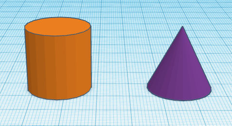
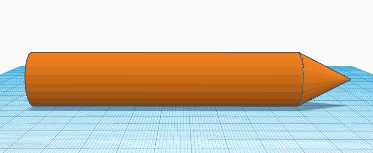
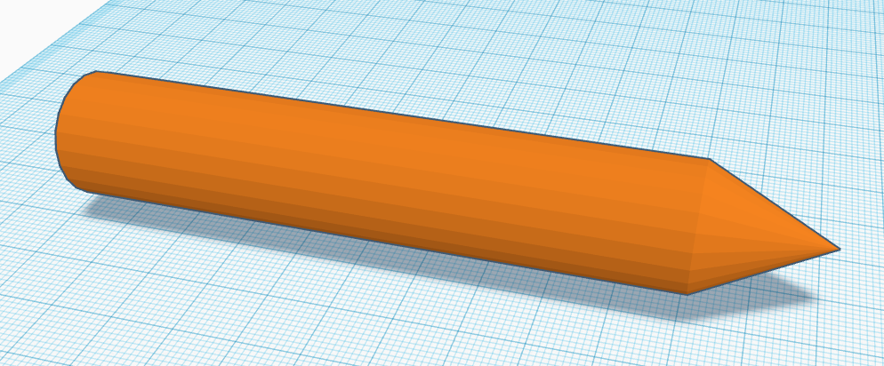
The aim of this set of exercises is to produce a model of a pencil.
-
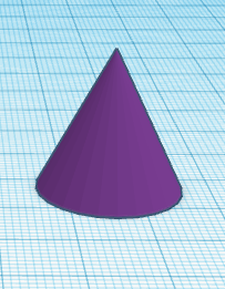
Move a cylinder and a cone from the Basic Shapes menu onto the workplane.
- Hold down the left mouse button on the shape you want from the menu and drag it onto the workplane.
- Hover your mouse cursor over a shape to identify it.
If you are still stuck, use the answer button below.
-
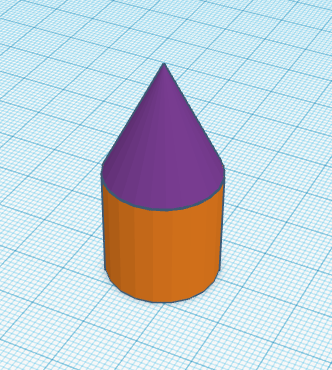
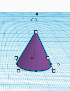
Position the cone on top of the cylinder, making sure it is central.
You may need to move your camera view as well as the shapes.
- The default height of the cylinder is 20mm. This means you will need to raise the cone up the same distance.
- Once at the correct height, you can position the cone on top of the cylinder. Remember, there are tools that can help with this (ruler and/or align).
If you are still stuck, use the answer button below.
-
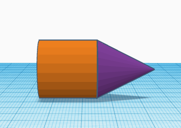
Rotate your model 90° to lay on its side and lower it back onto the Workplane.
- Remember, you can select both shapes by holding down the left mouse button whilst dragging a box around them.
- You could rotate the shapes separately, but that will then mean repositioning them toegther.
- You will need to lower the model back down to the Workplane surface.
If you are still stuck, use the answer button below.
-
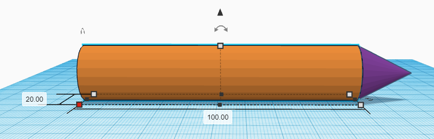
At the moment, our 'pencil' looks very stubby. To correct this, increase the length of the cylinder to 100mm.
- Make sure you only have the cylinder selected when you change the length. Otherwise, your cone will also be lengthened.
- There are two ways to change the length of the cylinder:
- You can click and drag one of the white squares until you have the right length, but this risks accidentally changing the width too.
- You can click on a white box to load up the measurements and then click in the correct measurement box where you can type in the value.
If you are still stuck, use the answer button below.
-
Now we want to merge our two shapes together to make a single pencil shape.
- You will need to have both shapes selected.
- There is a merge button on the top tool bar, or you can press CTRL + G.
- You will know it's worked when the whole model turns the same colour.
If you are still stuck, use the answer button below.
-
If we take a closer look at where the shapes join, we can see that they do not meet smoothly. This is due to the default settings of the original shapes. We need to undo the merging and then make sure both the shapes have the same number of sides (22) before merging them again.
- To undo our merging we can either use the undo arrow on the top tool bar, or press CTRL + Z. Both of these options will undo the previous action. Alternatively, you can select your pencil shape and use the Ungroup button on the toolbar (or use the keyboard shortcut which is CTRL + SHIFT + G).
- When you select a shape a menu box appears on the left of the Workplane. This has an option for number of sides.
- If you cannot see the number of sides in the menu box, you still have both shapes selected.
- To change the number of sides, you can either use the slider or select the value and type the value you want.
- Once you have set both shapes to 22 sides, merge them together again.
If you are still stuck, use the answer button below.
Before beginning this section, you will need to create a new design. The models created in Tinkercad autosave. To exit a file and return to your homepage, click on the Tinkercad logo in the top left.
These exercises will involve recreating several different combinations of shapes. They all use the default size of the shapes from the menu.
-
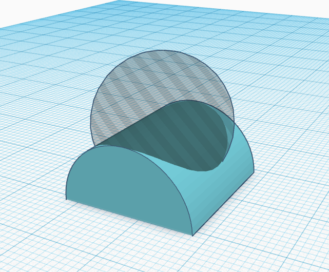
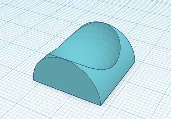
Can you use the two shapes shown on the left of the below image to create the shape on the right?
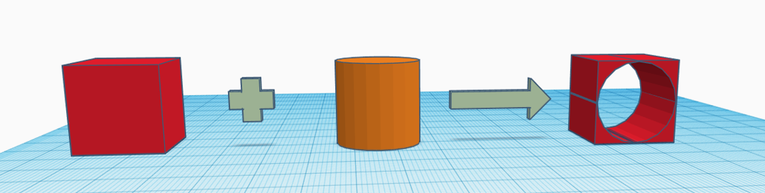
- You will need to rotate either the cylinder or the finished shape.
- The cylinder will need to be made into a hole.
- Remember to merge.
If you are still stuck, use the answer button below.
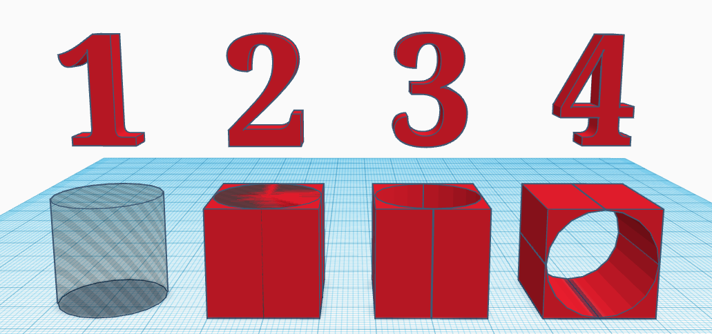
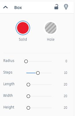
- Make the cylinder hollow.
- Position the cylinder centrally in the box.
- Merge the shapes.
- Rotate the new shape.
-
Can you use the two shapes shown on the left of the below image to create the shape on the right?
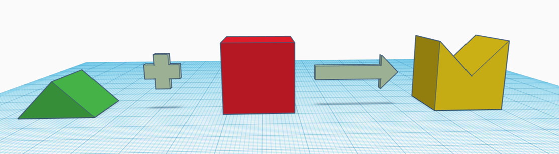
Tip: To match the result exactly, you will need to change the colour of the final shape.
- The triangular prism (labeeled as 'roof' in the Tinkercad menu) is the shape that needs to be made a hole.
- Clicking on the solid option in a shape's menu. allows you to select a colour for the final shape.
If you are still stuck, use the answer button below.
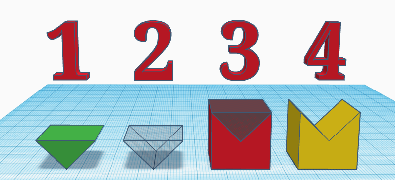
- Rotate the triangular prism 180°
- Make it hollow/a hole.
- Position this on top of the cube
- Merge the shapes together and change the colour to yellow
-
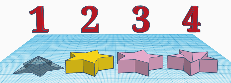
Can you use the two shapes shown on the left of the below image to create the shape on the right?
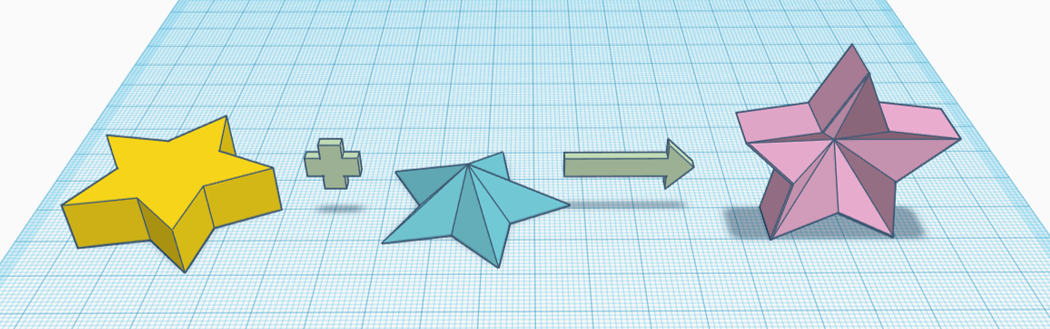
- To avoid alignment issues, create the shape before flipping over.
If you are still stuck, use the answer button below.
- Make the blue star into a hole.
- Place the yellow star shape over the top.
- Merge the stars together and change the colour to pale pink.
- Flip the model over.
-
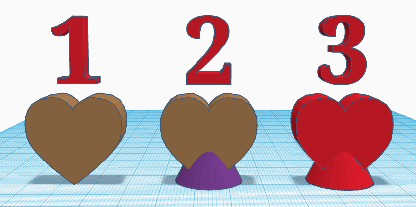
Using two shapes from the basic shapes menu in Tinkercad, recreate this model:
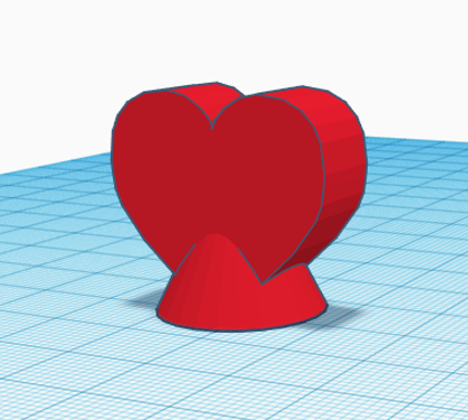
- This model requires the heart and cone shapes.
- Using the ruler or align tools will make it easier to position the shapes correctly.
If you are still stuck, use the answer button below.
- Rotate the heart shape to a vertical position.
- Position a cone centrally to the heart shape.
- Merge the shapes together and set the colour to red.
-
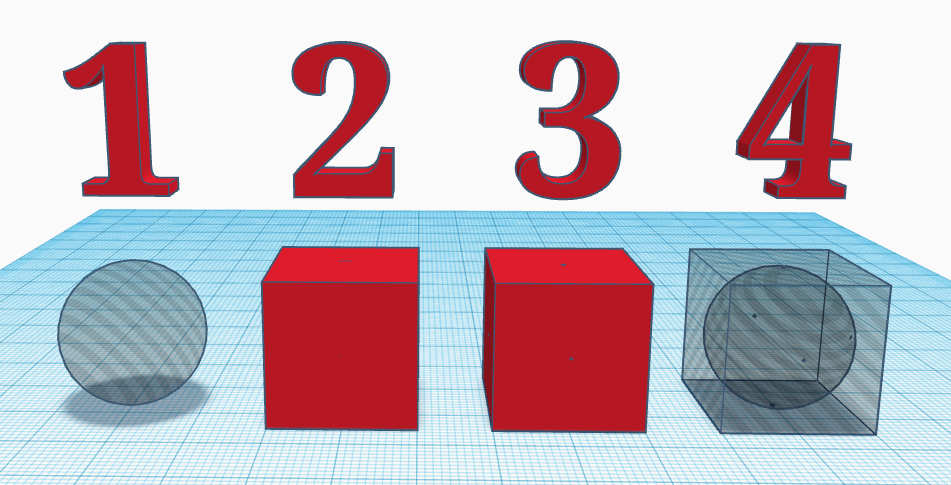
Using two shapes from the basic shapes menu in Tinkercad, recreate this model:
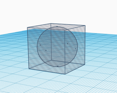
- You will need to merge a solid cube/box with a sphere shaped hole first.
- Merged shapes can also be changed to a hole.
- To test your success, merging the completed shape with an aligned solid cube will produce a solid sphere.
If you are still stuck, use the answer button below.
- Create a hollow sphere.
- Position a solid cube centrally over the sphere.
- Merge the shapes together.
- Make your model into a hole.
-
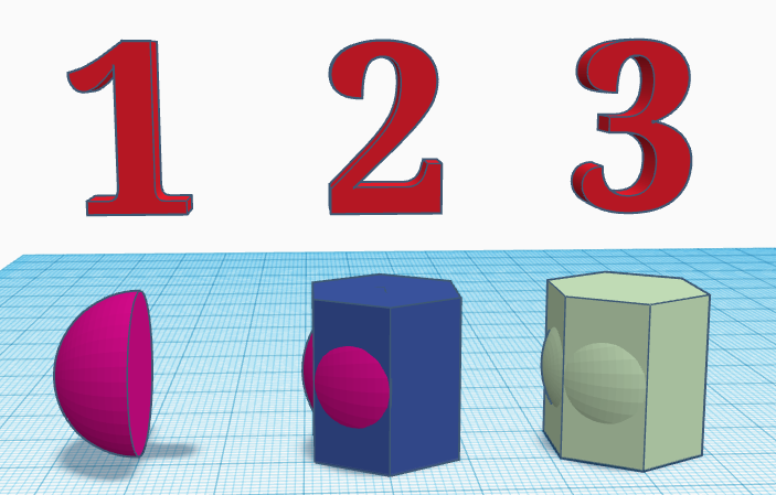
Using two shapes from the basic shapes menu in Tinkercad, recreate this model:
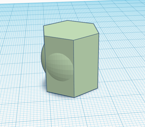
- Only three of the hexagonal sides have domes present - so, look for a shape in the menu that is only halve a sphere.
- The alignment is slightly different as the two shapes are not centrally positioned against each other.
If you are still stuck, use the answer button below.
- Rotate the half-sphere shape to positon it with the dome facing to the left.
- Place a polygon (hexagonal prism) so the centre of the half-sphere's flat side aligns with the centre point of the polygon.
- Merge the shapes together and change the colour to pale green.
-
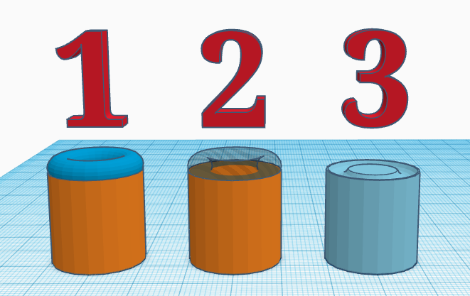
Using two shapes from the basic shapes menu in Tinkercad, recreate this model:
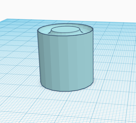
- You will need a cylinder and a torus from the shapes menu.
- The shapes are centrally aligned at different heights.
- Make sure the torus is at a height where the join is smooth but still produces an indent.
If you are still stuck, use the answer button below.
- Create a cylinder with a torus positioned with less than half of it overlapping.
- Make the torus shape into a hole.
- Merge the shapes together and change the colour of the model to pale blue.
-
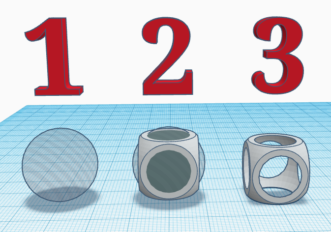
Using two shapes from the basic shapes menu in Tinkercad, recreate this model:
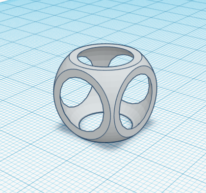
- There is a dice shape available at the bottom of the basic shapes menu in Tinkercad.
If you are still stuck, use the answer button below.
- Create a sphere shaped hole.
- Position a dice centrally over the sphere.
- Merge the shapes together and lower onto the Workplane.
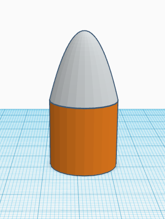
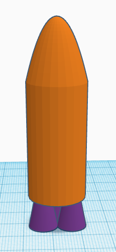
In a new Tinkercad file, follow the below steps to create a model space rocket, or create your own.
-
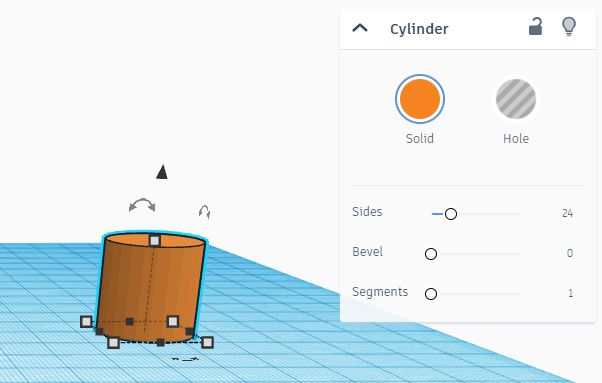
Add a cyclinder to the Workplane and set the number of sides to 24.
-
Place a paraboloid centrally on top of the cylinder.
-
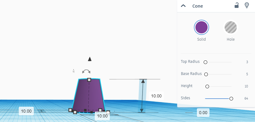
Create a separate cone shape with a top radius of 3mm, base radius of 5mm, and a height of 10mm
-
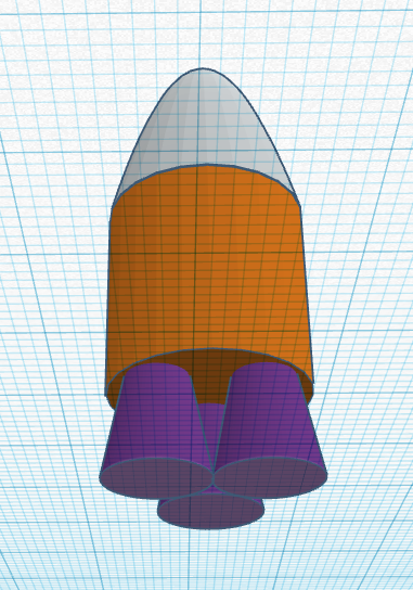
You will need two more of these cone shapes. Then, arrange the three 'thrusters' tightly together in a trianglular arrangement, before placing the model from step 2 centrally on top of them.
-
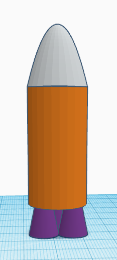
Increase the height of the cylinder to 40mm and raise the paraboloid to sit back on top again.
-
Merge the cylinder and parboloid into a single shape.
-
Increse the height of our newly merged shape to 80mm.
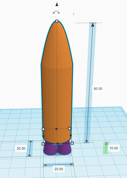
-
Create a separate paraboloid shape with a length of 60mm, height of 60mm, and a width/depth of 6mm.
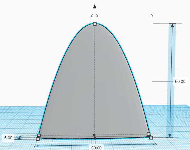
-
Position this new shape inside the rocket so its central base point is the same as the base central point of the cylinder.
-
Create a seperate cylinder hole shape which has a radius of 5mm and a height of 3mm.
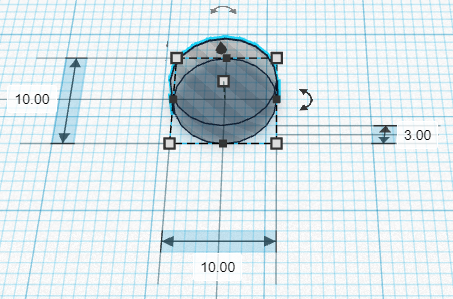
-
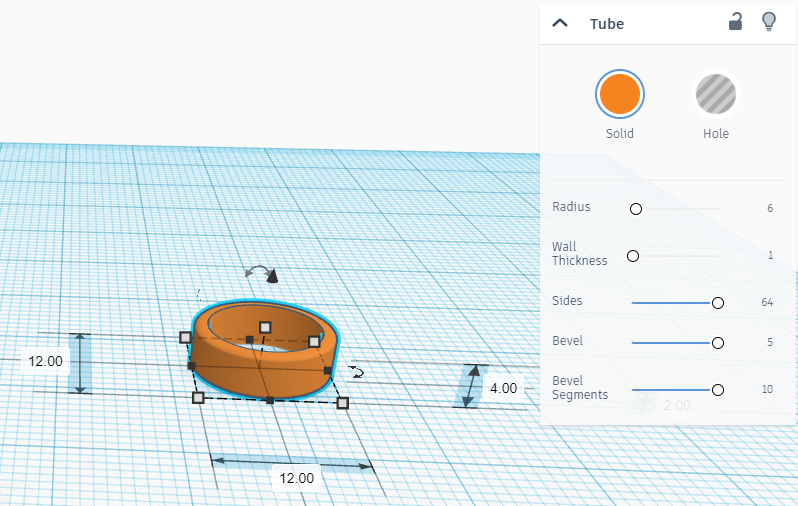
Create a seperate tube shape with a radius of 6mm, a wall thickness of 1mm, 64 sides, bevel set to 5 and bevel segments set to 10.
Tip: This can all be set in the tube settings menu.
-
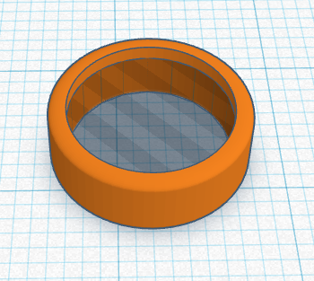
Place the hole made in step 10 inside this tube with their bases at the same level.
-
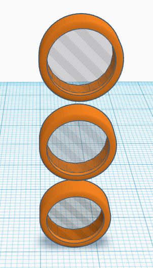
Flip the cylinder hole and tube together to stand on edge (90°). Create two more copies and have them placed directly above the original, in a column, with a 2mm gap between each one.
-
Position these 'portholes' on the front of your rocket model, 10mm up the cylinder.
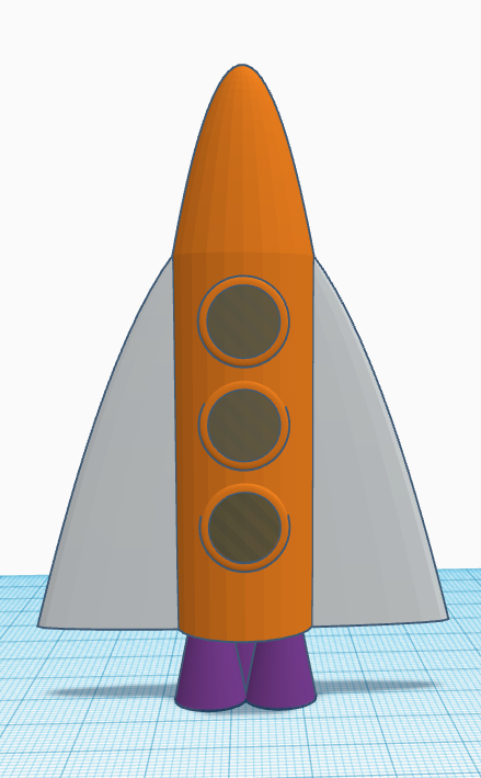
-
Once you are happy with the positioning of the 'portholes' on the front of your rocket (having no gaps between the tubes and the cylinder), merge them with the main body of the rocket.
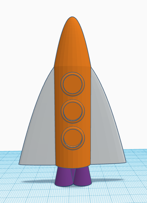
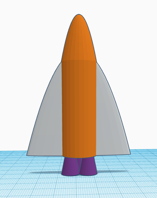
-
You now have a model rocket! Feel free to make your own changes to the model and/or decorate it.
Tip: Check out the 'Structures and Scenery' menu of shapes (click on the drop-down labelled 'Basic Shapes' at the top of the menu panel).