
This activity will introduce learners to the basic concepts of building, drawing, and programming circuits.
We have included exercises designed to use a free in-browser software called TinkerCad - this requires a TinkerCad account, or you can log in using an existing Google, Apple, Microsoft, or Facebook account.
Click on the below headings to expand each section.
A circuit is a system around which electricity can flow.
Electricity flows away from the negative end of a power supply (such as a battery) and towards the positive.
This means that the circuit must loop all the way around. Any breaks/gaps in the system will stop the flow of electricity.
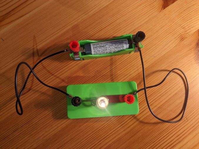
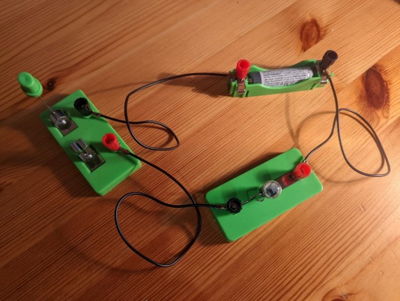
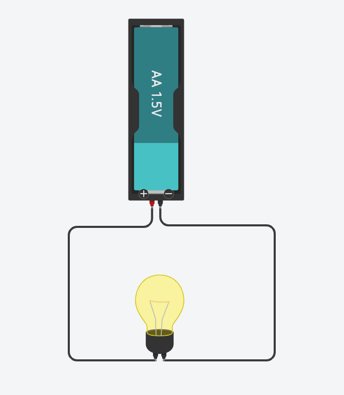
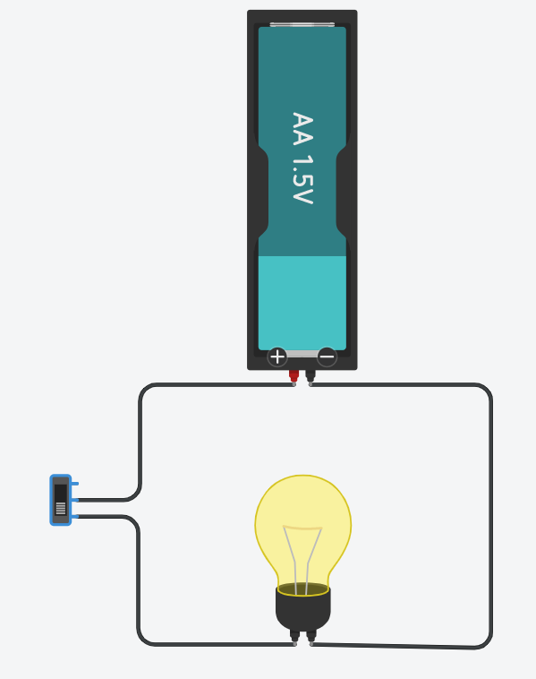
For example, the below circuit shows no power reaching the lightbulb, this is because we've broken the circuit by opening the switch on the left.
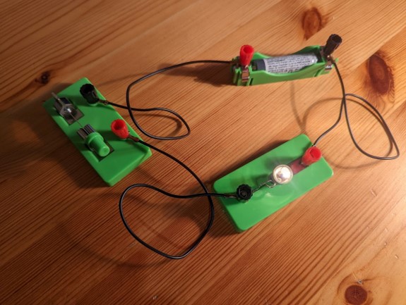
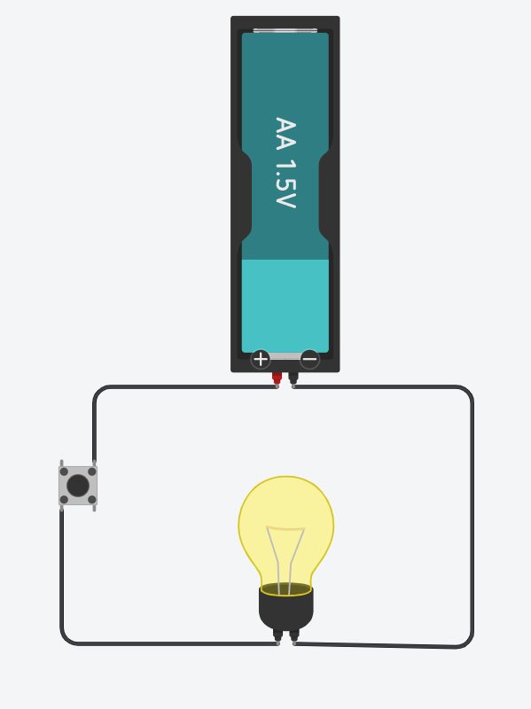
If we close the switch, completing the circuit, electricity can flow again, turning the light on.
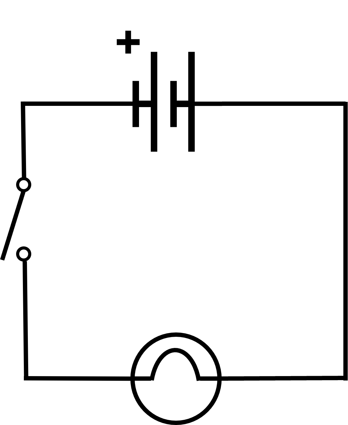
How would you draw this circuit?
To make things easier to both draw and understand, a standard system is used by scientists and engineers.
This circuit would be drawn as:

The wires are shown as straight lines with 90° corners.
When drawing circuits, you should always use a ruler.
The battery is drawn like this:

The shorter lines indicate the positive end of the battery.
In this example circuit we are using a filament lightbulb.
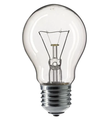
A filament lightbulb creates light by passing electricity through a very thin piece of wire that gets very hot and glows, producing light.
The symbol for a filament lightbulb is a circle where the wires enter slightly on both sides and are then joined by a half-circle arc:

You may have come across this symbol:

This is the symbol used to show any type of lightbulb.
A switch has different symbols to show whether it is open or closed.
An open switch:

A closed switch:

Let us look at an example of how switches are included in our circuit diagrams.
Open Switch
Closed Switch

TinkerCad is free software that can allow users to build and test circuits in a simulation.
To get started, go to www.tinkercad.com.
In the top right select Log In. A new menu will appear, select Personal accounts, and then choose a log in method. The more sign-in options include Microsoft, meaning most school accounts can be used for this. If you do not have any of these accounts, then select the Join Tinkercad option and create an account with them (free of charge).
Once you've logged in, you will need to select designs from the left menu and then + New in the top right, before selecting Circuit from the drop-down produced.
You can click and drag the components you want to use from the menu onto the main work area.
To create wires, you click on a component's connection point to start (for example, the negative point on a battery). When you click on the connection of another component the wire will join the two (such as a terminal on a lightbulb). You can create corners in a wire by selecting it, double clicking on a part of it and then dragging the new circle point to where you want the wire to bend.
Once you've completed your circuit, you can test it using the Start Simulation button above the component menu.
Note: The circuit cannot be altered whilst the simulation is running.
Can you recreate this circuit in TinkerCad?
Note: To find the lightbulb component you will need to change the components menu to All instead of Basic or use the search bar.
This is one possible solution:
Note: With a filament lightbulb, it doesn't matter which way round it is wired.
Can you recreate this circuit in TinkerCad?
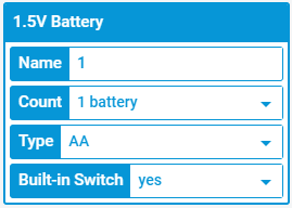
Hint: Instead of trying to find a switch in the component menu, you can select the battery in your circuit and, in the pop-up blue menu, set Built-in Switch to yes.
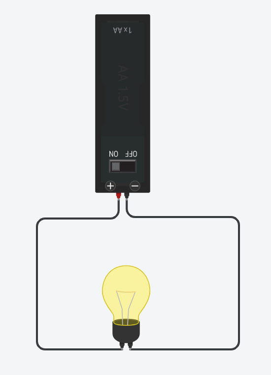
Here are three possible solutions:
Using the built-in switch on the battery
Using a slide-switch in the circuit
Using a push-button in the circuit - this allows the light to turn on only while the button is pressed down.
The speed/rate of the flow of electricity in a circuit is called the current. This is measured in Amperes/Amps using a device called an Ammeter.
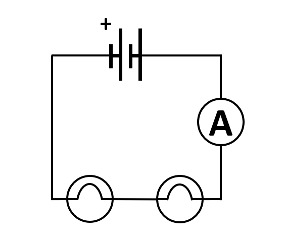
The circuit diagram symbol for an Ammeter is an A in a circle. We can connect this anywhere in the circuit.
So, if I wanted to measure the current in a circuit that just contained a battery and a filament lightbulb, this is what the diagram would look like:
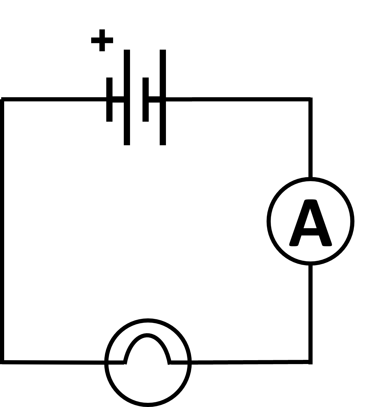
It doesn't matter where in this circuit we insert the Ammeter because the electricity will be flowing at the same rate at all points.
Note: If you get a negative value on your Ammeter, it means the wires are the wrong way round.
TinkerCad does not have a separate Ammeter in the component menu. Instead, it has a Multimeter which can be set to read current by changing the Mode to Amperage in the component settings.

First, let us measure the current of a 1.5V AA battery in TinkerCad.
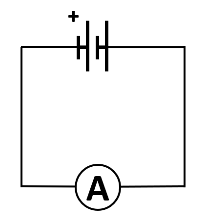
What is the current flowing around our circuit?
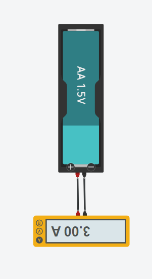
This shows us that the current is 3A (Amps/Amperes) for this battery.
Recreate this circuit in TinkerCad:
What is the current of this circuit?
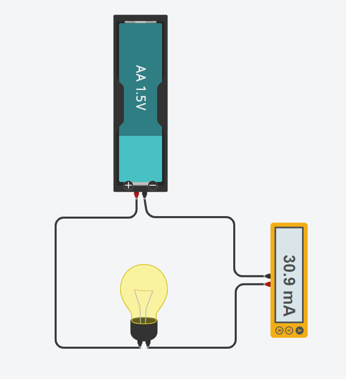
The Ammeter tells us that the current in this circuit is now 30.9mA (milli-Amperes) which is the same as 0.0309 Amperes.
Add a second lightbulb to the circuit in TinkerCad.
What is the current now?
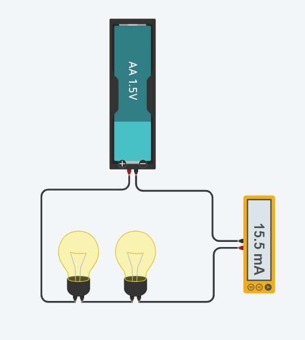
The Ammeter now tells us the current has gone down to 15.5mA.
The amount of energy being carried and used by components in a circuit is called the voltage. So a 1.5V battery supplies 1.5V (Volts) of energy to the circuit. This can be measured using a Voltmeter.
When we use a Voltmeter in a circuit, we are measuring how many volts a component is using. This means a Voltmeter is attached to a circuit either side of the component we're investigating, rather than inside the circuit like an Ammeter.
The circuit diagram symbol for a Voltmeter is a V in a circle.
So, if we want to know how much energy a lightbulb is using in a circuit, we connect a Voltmeter both before and after it.
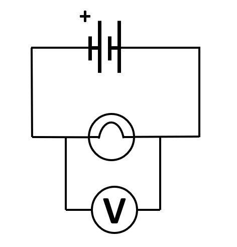
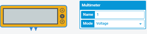
TinkerCad does not have a separate Voltmeter in the component menu. Instead, it has a Multimeter which can be set to read voltage by changing the Mode to Voltage in the component settings.
Create the below circuit in TinkerCad.
Note: In TinkerCad you cannot create a wire junction like those used in the circuit diagram. Instead you connect the Multimeter to the lightbulb's terminals/connectors.
What is the voltage across the lightbulb?
Note: If the Voltmeter gives you a negative value, it means the wires are the wrong way round
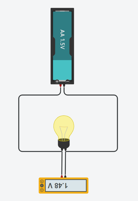
This tells us that the lightbulb in this circuit is using 1.48 Volts.
Create this circuit in TinkerCad:

Add a Multimeter to each lightbulb to measure the voltage.
How much voltage does each lightbulb use?
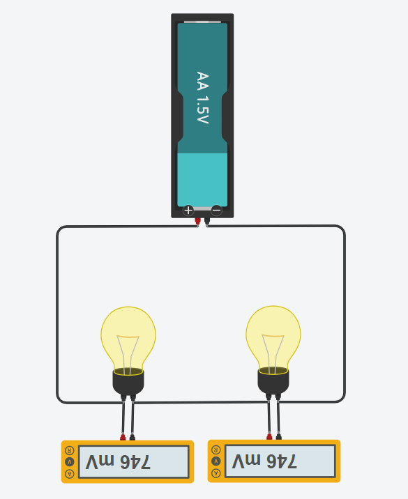
The voltage for each lightbulb is 746mV (milli-Volts) which is 0.746 Volts.
If you were to build these circuits in real life, what would you notice about the lightbulb brightness for one in a circuit compared to two?
The more lightbulbs in a circuit, the dimmer they would appear until there were too many for the battery to power - then they would all fail.
When we did the exercises in the current section, we noticed that the lightbulbs slowed the flow of electricity around the circuit. This is because they added resistance.
Filament lightbulbs have a lot of resistance because they produce light by 'squeezing' the electricity through a very fine strip of metal to produce heat and light.
It's not just filament lightbulbs. All components, even wires, add some type of resistance to a circuit, slowing down the flow of the electricity around the circuit.
The resistance of a component is measured in Ohms (Ω).
This value can be calculated using Ohm's Law:
Voltage = Current x Resistance.
This equation can be rearranged:
Resistance = Voltage ÷ Current.
So, the longer the wires, and the larger the number of components, the more resistance in the circuit.
This may sound like a bad thing, but some components need a lower current to work. If the current is too high, it can break the component or shorten its lifespan.
LEDs are one of the components requiring a low current to operate.
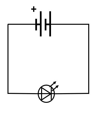
An LED has two connections - an anode and a cathode. The anode connects to the positive of the battery, the cathode to the negative.
The diagram symbol for an LED is:

Recreate this circuit in TinkerCad using a 3V power supply:
Here are two possible solutions:
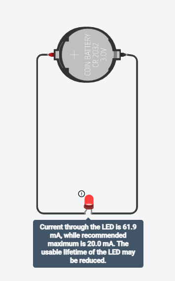
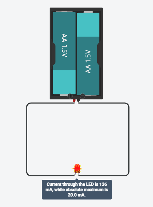
Note: If your LED does not light up when you start the simulator, the wires are probably connected the wrong way round. Remember: Anode connects to the positive, cathode to the negative.
This exercise shows how important a lower current is for some components. In this case we either shortened the lifespan of an LED or blew it up. Thankfully this is a simulator, so we don't need to buy replacement LEDs.
So how can we reduce the current in a circuit to support LEDs and other sensitive components?
We need to add some resistance to slow the flow of the electricity.
To do this, we can use a component call a resistor.
Resistors come in lots of different strengths. The higher the resistor value, the lower the current.
It doesn't matter whether a resistor goes before or after a component in a circuit. Consider the flow as a string loop rotating, it has only one speed, which is determined by the total resistance of the circuit.
The circuit diagram symbol for a resistor is simply an empty rectangle, normally with its value written next to it.
Recreate this circuit in TinkerCad:

Note: 1kΩ (1000Ω) is the default resistor on TinkerCad. You can alter the resistance in the resistor settings.
A possible solution:
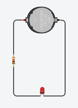
The LED now lights up without any warnings.