
THIS PAGE IS UNDERGOING CHANGES - PLEASE RETURN SHORTLY
An online activity on how to design, create, and program electonic cicruits using Tinkercad.
We have designed this to follow on directly from our Introduction to Circuits using Tinkercad activity.
As we shall be using BBC Micro:Bits as the programmable controller in this session, we would recommend those of you unfamiliar with this computer to visit our Online Micro:Bit Workshop Series first.
Click on the below headings to expand or collapse each section.
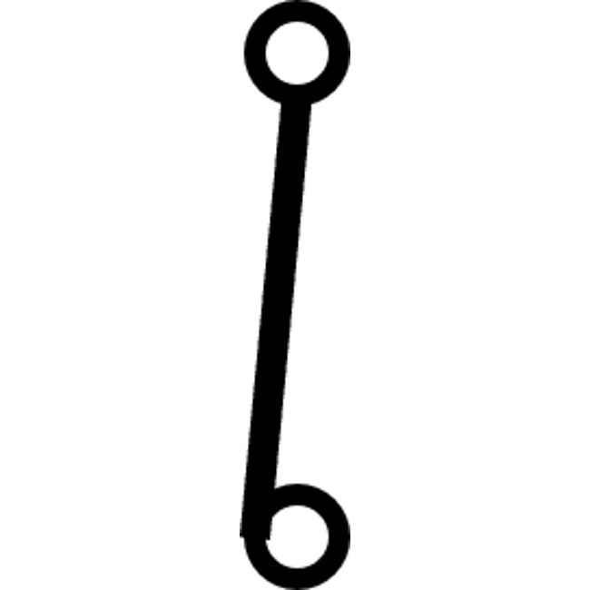
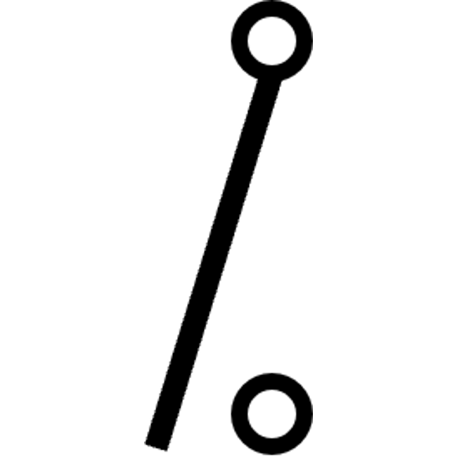
Before we begin, test yourself with the following circuit diagram symbols, how many can you identify?


Recreate this circuit in Tinkercad:

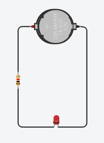
Using 2 AA batteries instead of the button battery is also correct.
We shall be looking at a range of different electronic components, some are inputs and others are outputs.
It is important to know the difference, especially when writing a program.
Input: A device/component which sends signals (information) to the computer.
Output: A device/component which receives signals (information) from the computer.
Try and identify whether these computer components are inputs or outputs. Click on each component to reveal the answer.
INPUT
INPUT
OUTPUT
INPUT
INPUT
OUTPUT
It is also possible for a device/component to be both an input and an output. For example, a touchscreen is both as it has touch input and image output.
Now let us look at the components on a BBC Micro:Bit.
Inputs
Buttons A and B
Light sensor
Radio antenna
Accelerometer/Movement sensor
Compass
Touch sensor (v2 only)
Microphone/Sound sensor (v2 only)
Outputs
LEDs
Radio antenna
Speaker (v2 only)
Notice how the radio antenna is both an input and an output device. This is because it can both receive and send radio signals.
A BBC Micro:Bit can simply be used as a 3V power supply, with no programming required.
The GND pin acts as the negative terminal, whilst the 3V pin acts as a positive terminal.
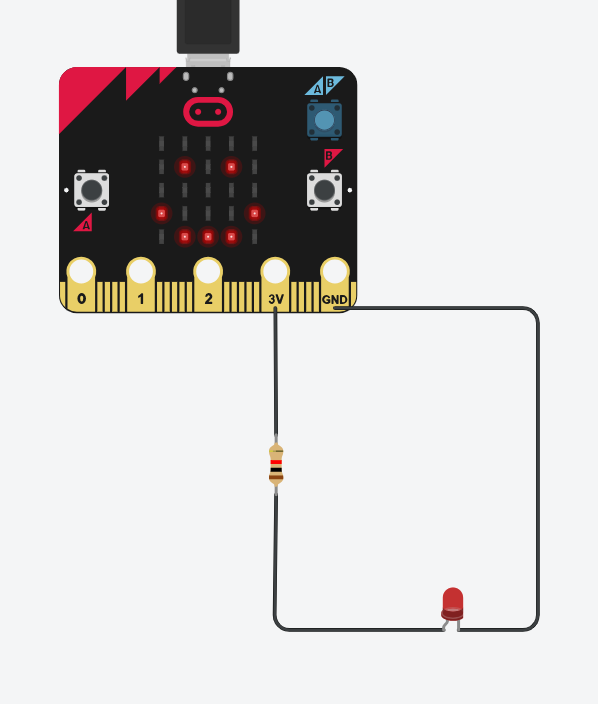
Recreate this circuit in Tinkercad to see this:
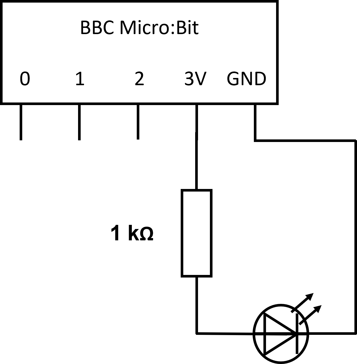
When you run the simulation the LED should light-up.
You should also see a smiley face appear on the Micro:Bit screen - this is due to the default code used by Tinkercad to show the Micro:Bit has power.
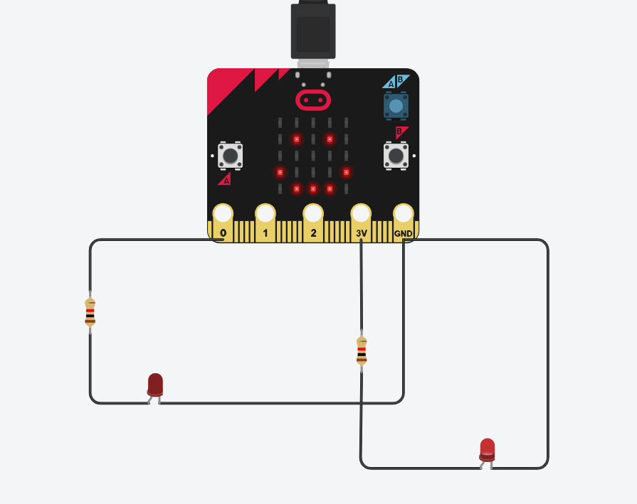
Now, update your circuit to match the one below:
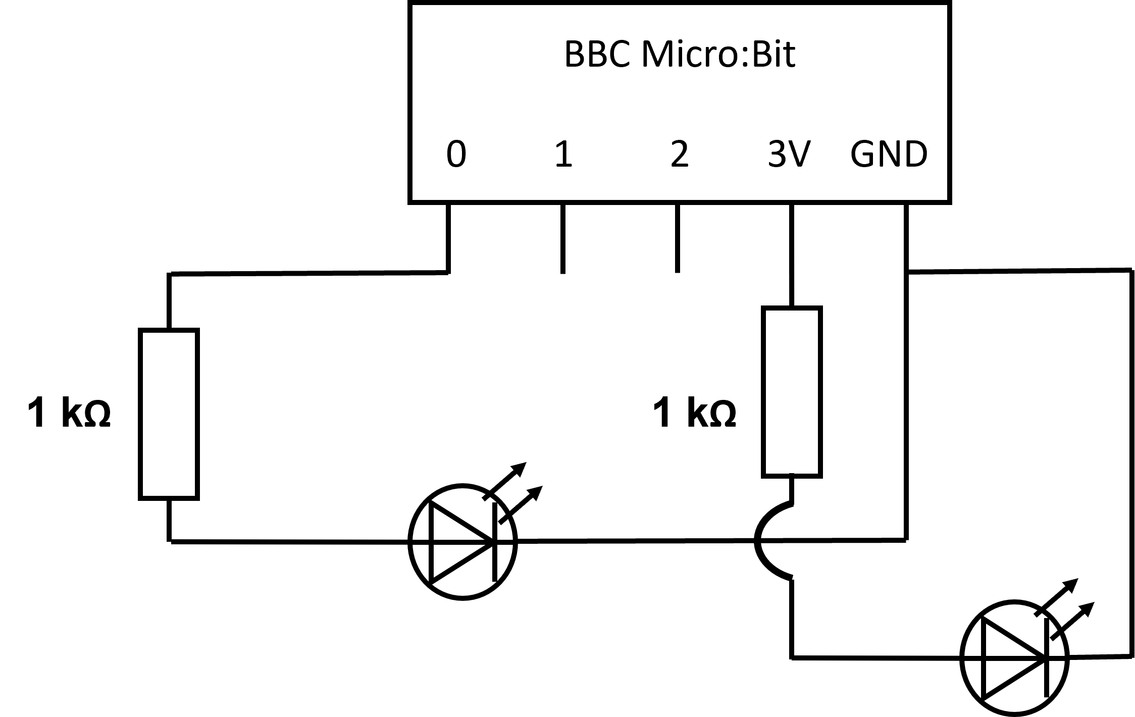
Have you noticed the arch in the wire? This is to illustrate that the wires are not connected - they are just crossing over each other.
When you run the simulator you will see that the LED connected to pin 0 does not light up.
This is because pins 0, 1, and 2 are programmable pins that require instruction from the Micro:Bit's program.
To access the programming editor on your circuit click on the code button (next to the start simulation button)
You can only access the code if you have a controller (Micro:Bit or Arduino) in the circuit build area.
We shall be using the Blocks option in the top left of this editor.
If you switch between blocks and text you will lose your program.
Remember that anything in the 'on start' loop only runs once when the program starts. Anything in the 'forever' loop will keep repeating until the program is exited.
You can click and drag the blocks from the side menu into your program.
You cannot edit your code if the simulation is running.
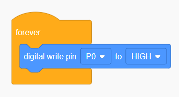
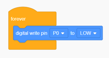
If a component only has two settings - on and off for example, this is a digital device. In Tinkercad we use a digital signal of HIGH to turn a component on. Setting the signal to LOW will turn the device off.
Here is an image of a basic Tinkercad program that will turn on a digital component connected to pin 0 on the Micro:Bit.
To turn off a digital component connected to the same pin we would change the HIGH to LOW:
If you haven't already, create this circuit:
Now open the block code window and program your Micro:Bit to make the LED connected to pin 0 flash on and off.
Tip: The LED is an output.
Tip: You will need to use pauses between turning on and off. If these are not included, the simulation will either make the LED appear to be permanently on or off as it's running through the code too fast.
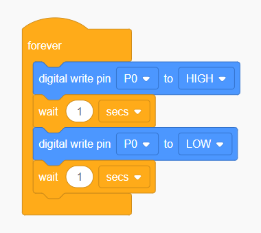
Note how we need a wait block after each signal change, not just one in the middle.
Digital commands work well for turning on and off devices or for reading key/button presses.
However a lot of components have a range of values they can send and/or receive. These are called analog components/devices.
For example, the BBC Micro:Bits built-in light sensor measures light level on a scale of 0 to 255. The higher the value, the brighter the light detected. The microphone uses the same range of values for sound, the higher the value, the louder the noise detected.
This means that we need to use programming instructions that have more options than just HIGH and LOW.
Let's say we have an analog output connected to pin 0 of our Micro:Bit and we want to change its value, we'd need to use this block:
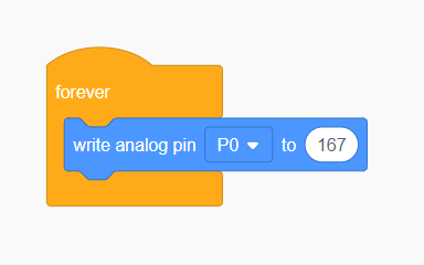
You will need to know the range of values for your component to ensure you only send a number that falls in it.
LEDs have the ability to be either a digital or an analog component.
How? Well, the LED has more options than just on and off, it can also shine at different brightness levels.
The full range of an LED is between 0 and 255. The higher the number, the brighter the LED will shine.
Returning to the circuit we created in the last exercise, replace the digital write blocks with analog write set to 255 and 0.
Tip: To delete blocks, click and drag them back into the block menu.
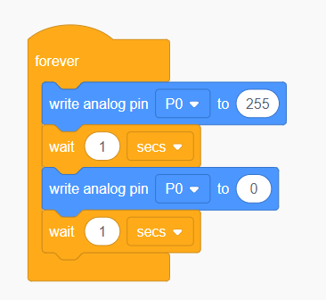
In the simulation, the program looks no different, because we're sending the same commands of fully on and fully off.
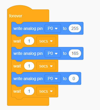
So, let us now have the LED flash on, somewhere in between (165 is a good mid-value), and then off.
Tip: Remember to add another wait block for whilst the LED is at this level too.
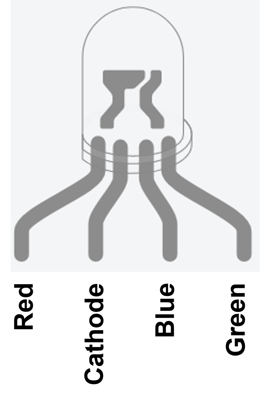
An RGB LED has three individually programmed colours (red, green, and blue). This allows the user to change the colour and/or choose a specific one.
To do this, the RGB LED has four pins, as shown below.
The RGB LED
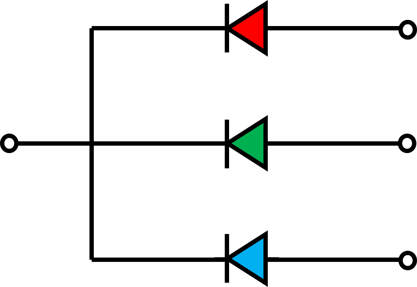
Circuit diagram symbol for an RGB LED
Now, create this circuit in Tinkercad:
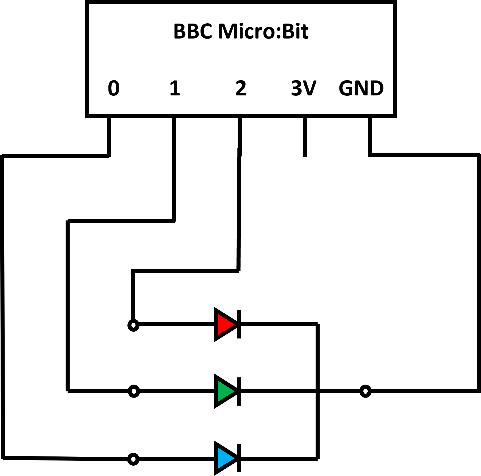
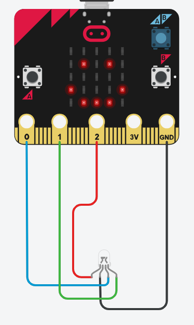
Note how I used different coloured wires to be able to easily see which colour is connected to each pin.
If you've re-used the Tinkercad file, then you'll need to delete the current code inside the forever loop.
We now need to write a program to activate this component in different ways.
Tip: You can use either the digital or analog options for this challenge. The provided answers use analog controls.
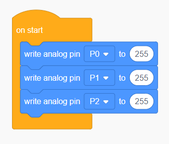
White light is produced by using the maximum value (255) for red, green, and blue.
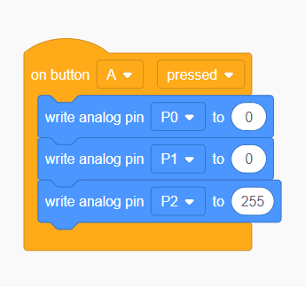
Tip: Button A is an input.
Tip: Set all three pins for this as we'll be using different colours on other inputs.
One pin should be set to 255, while the others are 0.
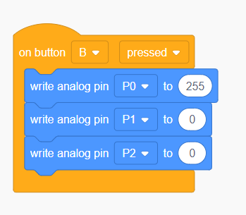
Yellow is a secondary colour of light, this means its a mix of two colours.
For more information on how rgb colour mixing works, you can check out our Colour Workshop.

The BBC Micro:Bit includes a built-in light sensor. In Tinkercad, different light levels can be set using a slide scale on the Micro:Bit's sensor panel, which activates when you start the simulation:
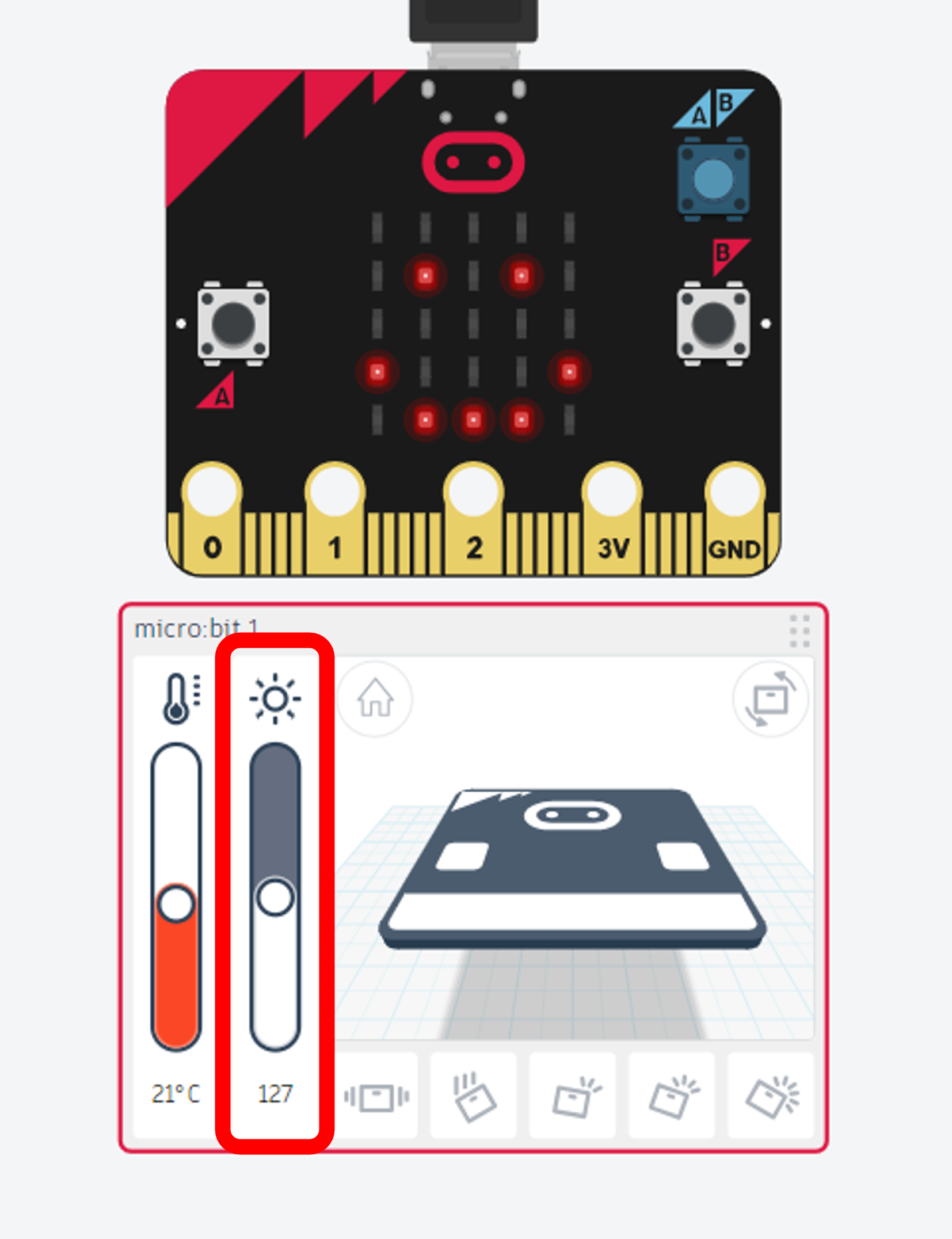
We need to program our circuit to use the light level reading the sensor collects.
First, we need to know the range of the sensor - in this case, 0 - 255. We also need to know what the values mean, for this sensor, the higher the reading, the brighter the light.
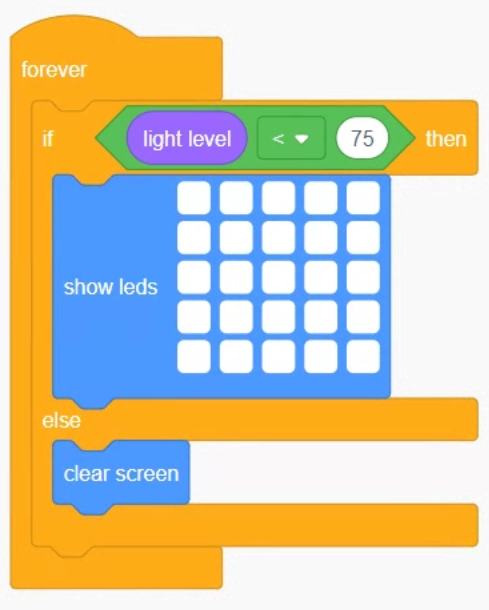
To have a circuit that reacts to a sensor reading, we will need to use an if-statement in the program.
Below is an example if statement made using a combination of blocks from the control, maths, and input menus. This program will have all the LEDs that make up the Micro:Bit's screen turn on when the light level detected is less than 75, otherwise the screen is cleared (all LEDs turned off). In effect, it makes the Micro:Bit into a torch that activates itself when it is dark.
Tinkercad only supports the first version of the Micro:Bit. This restricts how many built-in sensors we have available to experiment with.