
THIS PAGE IS UNDERGOING CHANGES - PLEASE RETURN SHORTLY
We have adapted the material created for our Robotics Club for anyone to work through at home or in school.
Each of the below sessions include a video lesson from one of our staff and a set of exercises to assess your understanding. As this page is for independent learners, answers are included.
We recommend that learners first visit our Online Micro:Bit Series for an introduction to programming, and our Online Electronics Series to better understand both hardware and software used.
Please select a session heading to get started.
You will need to copy our 'Valiant' Robot Tinkercad circuit into your Tinkercad account for these exercises.
As a reminder for how to log-in and use Tinkercad, please see Session One of our Online Electronics Series
These challenges involve getting started with our 'Valiant' robot programming.
All learners should start with the bronze level and work their way up as far as they can.
Click on each challenge heading to expand.
Important: Make sure you have the code panel on Tinkercad set to Text, as shown here:
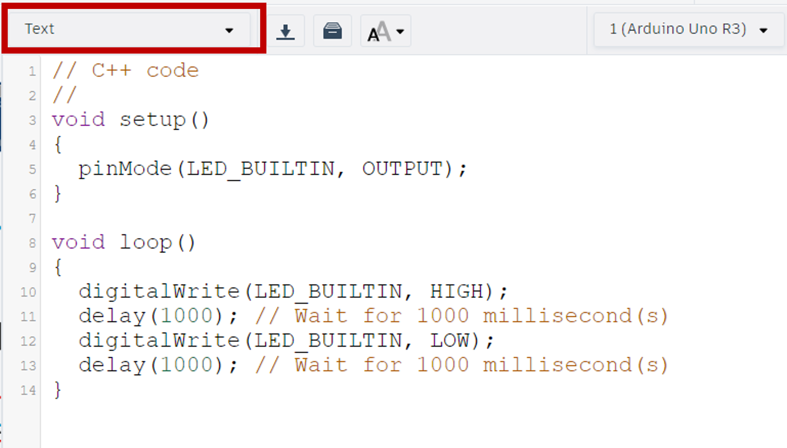
The program provided is Tinkercad's default Arduino program which turns the built-in LED on the Arduino on and off.
Delete the contents of the void setup() and void loop() so your start code looks like this:
    //C++ code
    //
    void setup ()
    {

    }

    void loop ()
    {

    }
void setup() (on start).
pinMode() to identify a pin in use and whether it is an INPUT or OUTPUT.pinMode() brackets we need to add the pin's number and that it's an OUTPUT.
If you are still stuck, please use the answer button below.
    //C++ code
    //
    void setup ()
    {
      pinMode(13, OUTPUT);
    }

    void loop ()
    {

    }
void loop() (forever loop) write the code to turn this LED on and off.
Tip: You will need to add a 100ms delay (wait) between light changes to observe them in the simulator.
digitalWrite() instructions to tell a digital component to turn on or off.digitalWrite() command we need to include the pin we're changing followed by HIGH or LOW.delay() instruction makes the program wait for the length of time stated inside the brackets - measured in milliseconds.void loop() acts the same as a forever loop.If you are still stuck, please use the answer button below.
    //C++ code
    //
    void setup ()
    {
      pinMode(13, OUTPUT);
    }

    void loop ()
    {
      digitalWrite(13, HIGH);
      delay(100);
      digitalWrite(13, LOW);
      delay(100);
    }
Tip: The LDR/Photoresistor is an analog input device.
void setup().pinMode() command as explained in the Bronze Level exercises.If you are still stuck, please use the answer button below.
    //C++ code
    //
    void setup ()
    {
      pinMode(13, OUTPUT);
      pinMode(A0, INPUT);
    }

    void loop ()
    {
      digitalWrite(13, HIGH);
      delay(100);
      digitalWrite(13, LOW);
      delay(100);
    }
Tip: Setting up the serial monitor was demonstrated in the video lesson.
Serial.begin() instruction inside the void setup().If you are still stuck, please use the answer button below.
    //C++ code
    //
    void setup ()
    {
      pinMode(13, OUTPUT);
      pinMode(A0, INPUT);
      Serial.begin(9600);
    }

    void loop ()
    {
      digitalWrite(13, HIGH);
      delay(100);
      digitalWrite(13, LOW);
      delay(100);
    }
Tip: These values are integers (whole numbers). This means we need to tell the program this is a variable with type int.
Important: Where we create a variable in the program decides where we can use it.
For this topic, we shall be using mainly Global Variables. These are variables we define at the very start of a program, even before the void setup(). This means we can then use them in any and all sections of the program.
If you were to create a variable inside a loop/function it would only be accessible inside that same loop/function and no-where else in the program. This would be called a Local Variable. Remember, this means the variable will be re-created every time the loop/function it is in runs.
If you are still stuck, please use the answer button below.
    //C++ code
    //
    int ldrValue = 0;

    void setup ()
    {
      pinMode(13, OUTPUT);
      pinMode(A0, INPUT);
      Serial.begin(9600);
    }

    void loop ()
    {
      digitalWrite(13, HIGH);
      delay(100);
      digitalWrite(13, LOW);
      delay(100);
    }
void loop(), have your new LDR variable equal to the LDR sensor reading. Then have the program print the value of this variable to the serial monitor.
Tip: The LDR is an analog input and is connected to pin A0.
analogRead() instruction with the pin identified inside its brackets.Serial.println() command tells the program to print whatever is in its brackets on a new line of the serial monitor.If you are still stuck, please use the answer button below.
    //C++ code
    //
    int ldrValue = 0;

    void setup ()
    {
      pinMode(13, OUTPUT);
      pinMode(A0, INPUT);
      Serial.begin(9600);
    }

    void loop ()
    {
      digitalWrite(13, HIGH);
      delay(100);
      digitalWrite(13, LOW);
      delay(100);
      ldrValue = analogRead(A0);
      Serial.println(ldrValue);
    }
The Tinkercad code editor has a built-in debugger. This lets us know when there is an error in the code and the type. It runs every time we start the simulation. In this exercise we will be introducing errors into our program to help us match them to the error messages.
Change your void setup() to match each of the below examples to see the error message produced.
Tip: the numbers at the beginning of the error messages may differ as they are referring to line numbers in the code which are dependent on your spacing.
1. Missing '}':
2. Missing '{':
    void setup ()

      pinMode(13, OUTPUT);
      pinMode(A0, INPUT);
      Serial.begin(9600);
    }
3. Missing ';':
    void setup ()
    {
      pinMode(13, OUTPUT);
      pinMode(A0, INPUT)
      Serial.begin(9600);
    }
4. Missing '()':
    void setup
    {
      pinMode(13, OUTPUT);
      pinMode(A0, INPUT);
      Serial.begin(9600);
    }
5. Spelling Mistake:
    void setup ()
    {
      pinMoed(13, OUTPUT);
      pinMode(A0, INPUT);
      Serial.begin(9600);
    }
6. Missing ',':
    void setup ()
    {
      pinMode(13 OUTPUT);
      pinMode(A0, INPUT);
      Serial.begin(9600);
    }
    In function 'void setup()':
    13:1: error: a function-definition is not allowed here before '{' token
    20:1: error: expected '}' at end of input
    7:3: error: expected initializer before 'pinMode'
    8:10: error: expected constructor, destructor, or type conversion before '(' token
    9:3: error: 'Serial' does not name a type
    10:1: error: expected declaration before '}' token
      In function 'void setup()':
    9:3: error: expected ';' before 'Serial'
    5:6: error: variable or field 'setup' declared void
    7:22: error: expected '}' before ';' token
    8:10: error: expected constructor, destructor, or type conversion before '(' token
    9:3: error: 'Serial' does not name a type
    10:1: error: expected declaration before '}' token
      In function 'void setup()':
    7:3: error: 'pinMoed' was not declared in this scope
    7:3: note: suggested alternative: 'pinMode'
    1:0:
      In function 'void setup()':
    44:16: error: expected ')' before numeric constant


    7:14: note: in expansion of macro 'OUTPUT'
    7:20: error: too few arguments to function 'void pinMode(uint8_t, uint8_t)'
    1:0:
    134:6: note: declared here
These exercises continue using the program developed in Session One.
All learners should start with the bronze level and work their way up as far as they can.
Click on each challenge heading to expand.
Tip: As we are still using the LED, so do not remove the pinMode setup.
If you are still stuck, please use the answer button below.
  //C++ code
  //
  int ldrValue = 0;

  void setup ()
  {
    pinMode(13, OUTPUT);
    pinMode(A0, INPUT);
    Serial.begin(9600);
  }

  void loop ()
  {
    ldrValue = analogRead(A0);
    Serial.println(ldrValue);
  }
Tip: If you successfully completed the first extension exercise in Session One, skip this step.
void setup().If you are still stuck, please use the answer button below.
  //C++ code
  //
  int blueLED = 13;
  int ldrValue = 0;

  void setup ()
  {
    pinMode(13, OUTPUT);
    pinMode(A0, INPUT);
    Serial.begin(9600);
  }

  void loop ()
  {
    ldrValue = analogRead(A0);
    Serial.println(ldrValue);
  }
Tip: Although A0 appears to be a mix of characters and letters, it is a pin's number and therefore recognised as an integer.
void setup().If you are still stuck, please use the answer button below.
void setup().void setup() and once in void loop().If you are still stuck, please use the answer button below.
void loop() that turns the LED on when the LDR reading is less than 160.
Tip: If you completed the extension exercises in Session One, you only need to change the condition for the if-statement.
digitalWrite commands with HIGH and LOW values.If you are still stuck, please use the answer button below.
  //C++ code
  //
  int ldr = A0;
  int blueLED = 13;
  int ldrValue = 0;

  void setup ()
  {
    pinMode(blueLED, OUTPUT);
    pinMode(ldr, INPUT);
    Serial.begin(9600);
  }

  void loop ()
  {
    ldrValue = analogRead(ldr);
    Serial.println(ldrValue);
    if (ldrValue < 160)
    {
      digitalWrite(blueLED, HIGH);
    }
    else
    {
      digitalWrite(blueLED, LOW);
    }
  }
Tip: The library/extension is called Servo.h
#include command to add a library/extension.void setup().#include instruction does not have a semi-colon (;) at the end.If you are still stuck, please use the answer button below.
  //C++ code
  //

  #include <Servo.h>

  int ldr = A0;
  int blueLED = 13;
  int ldrValue = 0;

  void setup ()
  {
    pinMode(blueLED, OUTPUT);
    pinMode(ldr, INPUT);
    Serial.begin(9600);
  }

  void loop ()
  {
    ldrValue = analogRead(ldr);
    Serial.println(ldrValue);
    if (ldrValue < 160)
    {
      digitalWrite(blueLED, HIGH);
    }
    else
    {
      digitalWrite(blueLED, LOW);
    }
  }
Tip: Additional libraries can have different ways to produce variables. In this case, we use the command Servo variableName; to add a servo.
If you are still stuck, please use the answer button below.
  //C++ code
  //

  #include <Servo.h>
  Servo myServo;

  int ldr = A0;
  int blueLED = 13;
  int ldrValue = 0;

  void setup ()
  {
    pinMode(blueLED, OUTPUT);
    pinMode(ldr, INPUT);
    Serial.begin(9600);
  }

  void loop ()
  {
    ldrValue = analogRead(ldr);
    Serial.println(ldrValue);
    if (ldrValue < 160)
    {
      digitalWrite(blueLED, HIGH);
    }
    else
    {
      digitalWrite(blueLED, LOW);
    }
  }
void setup() to tell the program which pin myServo is connected to.
Tip: The Servo library command for identifying pins is different again. You will need to use the command structure of servoName.attach(pin);
servoName.attach(pin); replace the servoName with myServo and the pin with servoPin.If you are still stuck, please use the answer button below.
  //C++ code
  //

  #include <Servo.h>
  Servo myServo;

  int servoPin = 12;
  int ldr = A0;
  int blueLED = 13;
  int ldrValue = 0;

  void setup ()
  {
    pinMode(blueLED, OUTPUT);
    pinMode(ldr, INPUT);
    Serial.begin(9600);
    myServo.attach(servoPin);
  }

  void loop ()
  {
    ldrValue = analogRead(ldr);
    Serial.println(ldrValue);
    if (ldrValue < 160)
    {
      digitalWrite(blueLED, HIGH);
    }
    else
    {
      digitalWrite(blueLED, LOW);
    }
  }
void loop(), write a program using myServo.write(angle); instructions to make the servo move between the angles of 0°, 90°, 180°, and back to 90°. Include one second delays after each movement.
Tip: the delay(); instruction uses milliseconds for the value inside the brackets. 1000 milliseconds = 1 second.
If you are still stuck, please use the answer button below.
  //C++ code
  //

  #include <Servo.h>
  Servo myServo;

  int servoPin = 12;
  int ldr = A0;
  int blueLED = 13;
  int ldrValue = 0;

  void setup ()
  {
    pinMode(blueLED, OUTPUT);
    pinMode(ldr, INPUT);
    Serial.begin(9600);
    myServo.attach(servoPin);
  }

  void loop ()
  {
    ldrValue = analogRead(ldr);
    Serial.println(ldrValue);
    if (ldrValue < 160)
    {
      digitalWrite(blueLED, HIGH);
    }
    else
    {
      digitalWrite(blueLED, LOW);
    }
    myServo.write(0);
    delay(1000);
    myServo.write(90);
    delay(1000);
    myServo.write(180);
    delay(1000);
    myServo.write(90);
    delay(1000);
  }
Tip: You will need to look at the circuit to identify which pin this is.
If you are still stuck, please use the answer button below.
  //C++ code
  //

  #include <Servo.h>
  Servo myServo;

  int piezo = A3;
  int servoPin = 12;
  int ldr = A0;
  int blueLED = 13;
  int ldrValue = 0;

  void setup ()
  {
    pinMode(blueLED, OUTPUT);
    pinMode(ldr, INPUT);
    Serial.begin(9600);
    myServo.attach(servoPin);
  }

  void loop ()
  {
    ldrValue = analogRead(ldr);
    Serial.println(ldrValue);
    if (ldrValue < 160)
    {
      digitalWrite(blueLED, HIGH);
    }
    else
    {
      digitalWrite(blueLED, LOW);
    }
    myServo.write(0);
    delay(1000);
    myServo.write(90);
    delay(1000);
    myServo.write(180);
    delay(1000);
    myServo.write(90);
    delay(1000);
  }
pinMode() for the buzzer inside the void setup().
Tip: You will need to consider if the buzzer is an input or output.
If you are still stuck, please use the answer button below.
  //C++ code
  //

  #include <Servo.h>
  Servo myServo;

  int piezo = A3;
  int servoPin = 12;
  int ldr = A0;
  int blueLED = 13;
  int ldrValue = 0;

  void setup ()
  {
    pinMode(blueLED, OUTPUT);
    pinMode(ldr, INPUT);
    Serial.begin(9600);
    myServo.attach(servoPin);
    pinMode(piezo, OUTPUT);
  }

  void loop ()
  {
    ldrValue = analogRead(ldr);
    Serial.println(ldrValue);
    if (ldrValue < 160)
    {
      digitalWrite(blueLED, HIGH);
    }
    else
    {
      digitalWrite(blueLED, LOW);
    }
    myServo.write(0);
    delay(1000);
    myServo.write(90);
    delay(1000);
    myServo.write(180);
    delay(1000);
    myServo.write(90);
    delay(1000);
  }
void loop() section of your program.tone(pin, frequency, duration);void loop().If you are still stuck, please use the answer button below.
  //C++ code
  //

  #include <Servo.h>
  Servo myServo;

  int piezo = A3;
  int servoPin = 12;
  int ldr = A0;
  int blueLED = 13;
  int ldrValue = 0;

  void setup ()
  {
    pinMode(blueLED, OUTPUT);
    pinMode(ldr, INPUT);
    Serial.begin(9600);
    myServo.attach(servoPin);
    pinMode(piezo, OUTPUT);
  }

  void loop ()
  {
    ldrValue = analogRead(ldr);
    Serial.println(ldrValue);
    if (ldrValue < 160)
    {
      digitalWrite(blueLED, HIGH);
    }
    else
    {
      digitalWrite(blueLED, LOW);
    }
    myServo.write(0);
    delay(1000);
    myServo.write(90);
    delay(1000);
    myServo.write(180);
    delay(1000);
    myServo.write(90);
    delay(1000);
    if (ldrValue < 60)
    {
      tone(piezo, 65, 500);
    }
    else if (ldrValue < 100)
    {
      tone(piezo, 82, 500);
    }
    else if (ldrValue < 160)
    {
      tone(piezo, 98, 500);
    }
    else if (ldrValue < 220)
    {
      tone(piezo, 131, 500);
    }
    else if (ldrValue < 280)
    {
      tone(piezo, 165, 500);
    }
    else if (ldrValue < 340)
    {
      tone(piezo, 196, 500);
    }
    else if (ldrValue < 400)
    {
      tone(piezo, 262, 500);
    }
    else if (ldrValue < 460)
    {
      tone(piezo, 330, 500);
    }
    else if (ldrValue < 520)
    {
      tone(piezo, 392, 500);
    }
    else
    {
      tone(piezo, 523, 500);
    }
  }
For these exercises we would advise that use a copy of your program in case things go wrong.
Mapping: As with the previous block coding in Makecode and Tinkercad, it is possible to map ranges of values from inputs to outputs instead of having such long if-statements.
For this we need to create a value to hold the mapping:
int mappedVariable = map(inputValue, inputMin, inputMax, outputMin, outputMax);
For example, if we wanted to map the range of a potentiometer (analog input) to an LED (analog output), making the LED brighter as the potentiometer value increases, we need the following information:
The program would look something like this:
Tip: The LDR range in the Tinkercad simulator is 6 to 679. The servo angle can be anything between 0 and 180.
The frequency range of the buzzer is 31 to 4978.
We shall be continuing on from the program produced in Session Two.
All learners should start with the bronze level and work their way up as far as they can.
Click on each challenge heading to expand.
These exercises will take you through how to set up motor functions for this robot.
A variable called leftForwardPin which is set to 10,
A variable called leftReversePin which is set to 11,
A variable called rightForwardPin which is set to 9,
A variable called rightReversePin which is set to 6.
void setup() so we can use them globally.If you are still stuck, please use the answer button below.
The section of the program altered is shown below. The full program will be added at the end of each level.
pinMode(leftForwardPin, OUTPUT);If you are still stuck, please use the answer button below.
The section of the program altered is shown below. The full program will be added at the end of each level.
  void setup ()
  {
    pinMode(leftForwardPin, OUTPUT);
    pinMode(leftReversePin, OUTPUT);
    pinMode(rightForwardPin, OUTPUT);
    pinMode(rightReversePin, OUTPUT);
    pinMode(blueLED, OUTPUT);
    pinMode(ldr, INPUT);
    Serial.begin(9600);
    myServo.attach(servoPin);
    pinMode(piezo, OUTPUT);
  }
Tip: The motors used in this circuit are digital devices.
void setup(). This will reduce the risk of accidentally mixing these new functions inside the existing program.
void functionName() { } with the instructions inside the curly brackets.
digitalWrite(); commands for each motor variable.
digitalWrite(); brackets, you will need to include the variable and whether it is HIGH or LOW.
  void forward()
  {
    digitalWrite(leftForwardPin, HIGH);
    digitalWrite(leftReversePin, LOW);
    digitalWrite(rightForwardPin, HIGH);
    digitalWrite(rightReversePin, LOW);
  }
If you are still stuck, please use the answer button below.
The section of the program altered is shown below. The full program will be added at the end of each level.
  int ldrValue = 0;

  void robotForward()
  {
    digitalWrite(leftForwardPin, HIGH);
    digitalWrite(leftReversePin, LOW);
    digitalWrite(rightForwardPin, HIGH);
    digitalWrite(rightReversePin, LOW);
  }

  void robotReverse()
  {
    digitalWrite(leftForwardPin, LOW);
    digitalWrite(leftReversePin, HIGH);
    digitalWrite(rightForwardPin, LOW);
    digitalWrite(rightReversePin, HIGH);
  }

  void robotLeft()
  {
    digitalWrite(leftForwardPin, LOW);
    digitalWrite(leftReversePin, HIGH);
    digitalWrite(rightForwardPin, HIGH);
    digitalWrite(rightReversePin, LOW);
  }

  void robotRight()
  {
    digitalWrite(leftForwardPin, HIGH);
    digitalWrite(leftReversePin, LOW);
    digitalWrite(rightForwardPin, LOW);
    digitalWrite(rightReversePin, HIGH);
  }

  void robotStop()
  {
    digitalWrite(leftForwardPin, LOW);
    digitalWrite(leftReversePin, LOW);
    digitalWrite(rightForwardPin, LOW);
    digitalWrite(rightReversePin, LOW);
  }

  void setup ()
  //C++ code
  //

  #include <Servo.h>
  Servo myServo;

  int leftForwardPin = 10;
  int leftReversePin = 11;
  int rightForwardPin = 9;
  int rightReversePin = 6;
  int piezo = A3;
  int servoPin = 12;
  int ldr = A0;
  int blueLED = 13;
  int ldrValue = 0;

  void robotForward()
  {
    digitalWrite(leftForwardPin, HIGH);
    digitalWrite(leftReversePin, LOW);
    digitalWrite(rightForwardPin, HIGH);
    digitalWrite(rightReversePin, LOW);
  }

  void robotReverse()
  {
    digitalWrite(leftForwardPin, LOW);
    digitalWrite(leftReversePin, HIGH);
    digitalWrite(rightForwardPin, LOW);
    digitalWrite(rightReversePin, HIGH);
  }

  void robotLeft()
  {
    digitalWrite(leftForwardPin, LOW);
    digitalWrite(leftReversePin, HIGH);
    digitalWrite(rightForwardPin, HIGH);
    digitalWrite(rightReversePin, LOW);
  }

  void robotRight()
  {
    digitalWrite(leftForwardPin, HIGH);
    digitalWrite(leftReversePin, LOW);
    digitalWrite(rightForwardPin, LOW);
    digitalWrite(rightReversePin, HIGH);
  }

  void robotStop()
  {
    digitalWrite(leftForwardPin, LOW);
    digitalWrite(leftReversePin, LOW);
    digitalWrite(rightForwardPin, LOW);
    digitalWrite(rightReversePin, LOW);
  }

  void setup ()
  {
    pinMode(leftForwardPin, OUTPUT);
    pinMode(leftReversePin, OUTPUT);
    pinMode(rightForwardPin, OUTPUT);
    pinMode(rightReversePin, OUTPUT);
    pinMode(blueLED, OUTPUT);
    pinMode(ldr, INPUT);
    Serial.begin(9600);
    myServo.attach(servoPin);
    pinMode(piezo, OUTPUT);
  }

  void loop ()
  {
    ldrValue = analogRead(ldr);
    Serial.println(ldrValue);
    if (ldrValue < 160)
    {
      digitalWrite(blueLED, HIGH);
    }
    else
    {
      digitalWrite(blueLED, LOW);
    }
    myServo.write(0);
    delay(1000);
    myServo.write(90);
    delay(1000);
    myServo.write(180);
    delay(1000);
    myServo.write(90);
    delay(1000);
    if (ldrValue < 60)
    {
      tone(piezo, 65, 500);
    }
    else if (ldrValue < 100)
    {
      tone(piezo, 82, 500);
    }
    else if (ldrValue < 160)
    {
      tone(piezo, 98, 500);
    }
    else if (ldrValue < 220)
    {
      tone(piezo, 131, 500);
    }
    else if (ldrValue < 280)
    {
      tone(piezo, 165, 500);
    }
    else if (ldrValue < 340)
    {
      tone(piezo, 196, 500);
    }
    else if (ldrValue < 400)
    {
      tone(piezo, 262, 500);
    }
    else if (ldrValue < 460)
    {
      tone(piezo, 330, 500);
    }
    else if (ldrValue < 520)
    {
      tone(piezo, 392, 500);
    }
    else
    {
      tone(piezo, 523, 500);
    }
  }
void loop() that calls our new functions when needed. We want our robot to do the following before moving its servo:
Tip: Use the delay(); instruction for the timings.
functionName(); instruction, replacing the function name to match the one you're calling.
robotForward(), robotReverse(), robotLeft(), robotRight(), and robotStop(). So, using these function names, if we wanted the robot to move forward for 5 seconds and then stop for 2 seconds before moving backwards for 5 seconds, we'd write:
  robotForward();
  delay(5000);
  robotStop();
  delay(2000);
  robotReverse();
  delay(5000);
  robotStop();
If you are still stuck, please use the answer button below.
The section of the program altered is shown below. The full program will be added at the end of each level.
  void loop ()
  {
    ldrValue = analogRead(ldr);
    Serial.println(ldrValue);
    if (ldrValue < 160)
    {
      digitalWrite(blueLED, HIGH);
    }
    else
    {
      digitalWrite(blueLED, LOW);
    }

    robotForward();
    delay(1000);
    robotStop();
    delay(500);
    robotLeft();
    delay(500);
    robotRight();
    delay(1000);
    robotLeft();
    delay(500);
    robotStop();
    delay(500);
    robotReverse();
    delay(1000);
    robotStop();
    delay(1000);

    myServo.write(0);
    delay(1000);
    myServo.write(90);
    delay(1000);
    myServo.write(180);
    delay(1000);
    myServo.write(90);
    delay(1000);
  //C++ code
  //

  #include <Servo.h>
  Servo myServo;

  int leftForwardPin = 10;
  int leftReversePin = 11;
  int rightForwardPin = 9;
  int rightReversePin = 6;
  int piezo = A3;
  int servoPin = 12;
  int ldr = A0;
  int blueLED = 13;
  int ldrValue = 0;

  void robotForward()
  {
    digitalWrite(leftForwardPin, HIGH);
    digitalWrite(leftReversePin, LOW);
    digitalWrite(rightForwardPin, HIGH);
    digitalWrite(rightReversePin, LOW);
  }

  void robotReverse()
  {
    digitalWrite(leftForwardPin, LOW);
    digitalWrite(leftReversePin, HIGH);
    digitalWrite(rightForwardPin, LOW);
    digitalWrite(rightReversePin, HIGH);
  }

  void robotLeft()
  {
    digitalWrite(leftForwardPin, LOW);
    digitalWrite(leftReversePin, HIGH);
    digitalWrite(rightForwardPin, HIGH);
    digitalWrite(rightReversePin, LOW);
  }

  void robotRight()
  {
    digitalWrite(leftForwardPin, HIGH);
    digitalWrite(leftReversePin, LOW);
    digitalWrite(rightForwardPin, LOW);
    digitalWrite(rightReversePin, HIGH);
  }

  void robotStop()
  {
    digitalWrite(leftForwardPin, LOW);
    digitalWrite(leftReversePin, LOW);
    digitalWrite(rightForwardPin, LOW);
    digitalWrite(rightReversePin, LOW);
  }

  void setup ()
  {
    pinMode(leftForwardPin, OUTPUT);
    pinMode(leftReversePin, OUTPUT);
    pinMode(rightForwardPin, OUTPUT);
    pinMode(rightReversePin, OUTPUT);
    pinMode(blueLED, OUTPUT);
    pinMode(ldr, INPUT);
    Serial.begin(9600);
    myServo.attach(servoPin);
    pinMode(piezo, OUTPUT);
  }

  void loop ()
  {
    ldrValue = analogRead(ldr);
    Serial.println(ldrValue);
    if (ldrValue < 160)
    {
      digitalWrite(blueLED, HIGH);
    }
    else
    {
      digitalWrite(blueLED, LOW);
    }

    robotForward();
    delay(1000);
    robotStop();
    delay(500);
    robotLeft();
    delay(500);
    robotRight();
    delay(1000);
    robotLeft();
    delay(500);
    robotStop();
    delay(500);
    robotReverse();
    delay(1000);
    robotStop();
    delay(1000);

    myServo.write(0);
    delay(1000);
    myServo.write(90);
    delay(1000);
    myServo.write(180);
    delay(1000);
    myServo.write(90);
    delay(1000);
    if (ldrValue < 60)
    {
      tone(piezo, 65, 500);
    }
    else if (ldrValue < 100)
    {
      tone(piezo, 82, 500);
    }
    else if (ldrValue < 160)
    {
      tone(piezo, 98, 500);
    }
    else if (ldrValue < 220)
    {
      tone(piezo, 131, 500);
    }
    else if (ldrValue < 280)
    {
      tone(piezo, 165, 500);
    }
    else if (ldrValue < 340)
    {
      tone(piezo, 196, 500);
    }
    else if (ldrValue < 400)
    {
      tone(piezo, 262, 500);
    }
    else if (ldrValue < 460)
    {
      tone(piezo, 330, 500);
    }
    else if (ldrValue < 520)
    {
      tone(piezo, 392, 500);
    }
    else
    {
      tone(piezo, 523, 500);
    }
  }
We are now going to setup and program the ultrasonic sensor.
If you are still stuck, please use the answer button below.
The sections of the program altered are shown below. The full program will be added at the end of each level.
  int ultrasonicTrigger = 7;
  int ultrasonicEcho = 8;
  int leftForwardPin = 10;
  int leftReversePin = 11;
  int rightForwardPin = 9;
  int rightReversePin = 6;
  int piezo = A3;
  int servoPin = 12;
  int ldr = A0;
  int blueLED = 13;
  int ldrValue = 0;
  void setup ()
  {
    pinMode(ultrasonicTrigger, OUTPUT);
    pinMode(ultrasonicEcho, INPUT);
    pinMode(leftForwardPin, OUTPUT);
    pinMode(leftReversePin, OUTPUT);
    pinMode(rightForwardPin, OUTPUT);
    pinMode(rightReversePin, OUTPUT);
    pinMode(blueLED, OUTPUT);
    pinMode(ldr, INPUT);
    Serial.begin(9600);
    myServo.attach(servoPin);
    pinMode(piezo, OUTPUT);
  }
Important: The ultrasonic sensor has a complicated setup which you do not need to worry about learning at this stage. Instead, we ask that you carefully copy the below calculation function into your program just after your motor functions but before the void setup();.
  int readUltrasonic()
  {
    digitalWrite(ultrasonicTrigger,LOW); // Clear the signal
    delayMicroseconds(2);
    digitalWrite(ultrasonicTrigger, HIGH); // Send out new signal
    delayMicroseconds(10);
    digitalWrite(ultrasonicTrigger,LOW); // Stop sending signal

    unsigned long duration = pulseIn(ultrasonicEcho, HIGH);
    int distance = duration /2 /29;
    Serial.print(distance);
    Serial.print("cm");
    return distance;
  }
This function gives us the distance to a detected object in centimetres. We can now call it in our program to help with the rest of this exercise.
Please note: If you used different variable names to those provided in step 1, this will not work.
The section of the program altered is shown below. The full program will be added at the end of each level.
myServo.write(0);
delay(1000);
myServo.write(90);
delay(1000);
myServo.write(180);
delay(1000);
myServo.write(90);
delay(1000);
readUltrasonic() function. Then, after it's moved to 90°, set the 'front' variable to call the same function. Repeat again for 180° with the 'right' variable. The fourth movement does not need a reading as we've already taken that one.
Tip: Remember, the delays are to allow the servos to finish their movements so the readings should be taken after the delay but before the next move.
myServo.write(0);
delay(1000);
left = readUltrasonic();
myServo.write(90);
delay(1000);
myServo.write(180);
delay(1000);
myServo.write(90);
delay(1000);
If you are still stuck, please use the answer button below.
The section of the program altered is shown below. The full program will be added at the end of each level.
myServo.write(0);
delay(1000);
left = readUltrasonic();
myServo.write(90);
delay(1000);
front = readUltrasonic();
myServo.write(180);
delay(1000);
right = readUltrasonic();
myServo.write(90);
delay(1000);
Tip: The readUltrasonic() function gives a distance in centimetres.
front < 100.If you are still stuck, please use the answer button below.
The section of the program altered is shown below. The full program will be added at the end of each level.
void loop(), create a set of instructions that will print into the serial monitor whether right or left is safer to travel in.
Tip: This will require an if-statement, an else if statement, and an else-statement. The else statement is used to capture when both measurements are the same.
Serial.println("word");If you are still stuck, please use the answer button below.
The section of the program altered is shown below. The full program will be added at the end of each level.
myServo.write(0);
delay(1000);
left = readUltrasonic();
myServo.write(90);
delay(1000);
front = readUltrasonic();
myServo.write(180);
delay(1000);
right = readUltrasonic();
myServo.write(90);
delay(1000);
if (right > left)
{
Serial.println("right");
}
else if (left > right)
{
Serial.println("left");
}
else
{
Serial.println("no problem");
}
//C++ code
//
#include <Servo.h>
Servo myServo;
  int left = 0;
  int front = 0;
  int right = 0;
  int ultrasonicTrigger = 7;
  int ultrasonicEcho = 8;
  int leftForwardPin = 10;
  int leftReversePin = 11;
  int rightForwardPin = 9;
  int rightReversePin = 6;
  int piezo = A3;
  int servoPin = 12;
  int ldr = A0;
  int blueLED = 13;
  int ldrValue = 0;
void robotForward()
{
digitalWrite(leftForwardPin, HIGH);
digitalWrite(leftReversePin, LOW);
digitalWrite(rightForwardPin, HIGH);
digitalWrite(rightReversePin, LOW);
}
void robotReverse()
{
digitalWrite(leftForwardPin, LOW);
digitalWrite(leftReversePin, HIGH);
digitalWrite(rightForwardPin, LOW);
digitalWrite(rightReversePin, HIGH);
}
void robotLeft()
{
digitalWrite(leftForwardPin, LOW);
digitalWrite(leftReversePin, HIGH);
digitalWrite(rightForwardPin, HIGH);
digitalWrite(rightReversePin, LOW);
}
void robotRight()
{
digitalWrite(leftForwardPin, HIGH);
digitalWrite(leftReversePin, LOW);
digitalWrite(rightForwardPin, LOW);
digitalWrite(rightReversePin, HIGH);
}
void robotStop()
{
digitalWrite(leftForwardPin, LOW);
digitalWrite(leftReversePin, LOW);
digitalWrite(rightForwardPin, LOW);
digitalWrite(rightReversePin, LOW);
}
int readUltrasonic()
{
digitalWrite(ultrasonicTrigger,LOW); // Clear the signal
delayMicroseconds(2);
digitalWrite(ultrasonicTrigger, HIGH); // Send out new signal
delayMicroseconds(10);
digitalWrite(ultrasonicTrigger,LOW); // Stop sending signal
unsigned long duration = pulseIn(ultrasonicEcho, HIGH);
int distance = duration /2 /29;
Serial.print(distance);
Serial.print("cm");
return distance;
}
void setup ()
{
pinMode(ultrasonicTrigger, OUTPUT);
pinMode(ultrasonicEcho, INPUT);
pinMode(leftForwardPin, OUTPUT);
pinMode(leftReversePin, OUTPUT);
pinMode(rightForwardPin, OUTPUT);
pinMode(rightReversePin, OUTPUT);
pinMode(blueLED, OUTPUT);
pinMode(ldr, INPUT);
Serial.begin(9600);
myServo.attach(servoPin);
pinMode(piezo, OUTPUT);
}
void loop ()
{
ldrValue = analogRead(ldr);
Serial.println(ldrValue);
if (ldrValue < 160)
{
digitalWrite(blueLED, HIGH);
}
else
{
digitalWrite(blueLED, LOW);
}
if (front < 100)
{
robotStop();
}
else
{
robotForward();
delay(1000);
robotStop();
delay(500);
robotLeft();
delay(500);
robotRight();
delay(1000);
robotLeft();
delay(500);
robotStop();
delay(500);
robotReverse();
delay(1000);
robotStop();
delay(1000);
}
  myServo.write(0);
  delay(1000);
  left = readUltrasonic();
  myServo.write(90);
  delay(1000);
  front = readUltrasonic();
  myServo.write(180);
  delay(1000);
  right = readUltrasonic();
  myServo.write(90);
  delay(1000);
if (right > left)
{
Serial.println("right");
}
else if (left > right)
{
Serial.println("left");
}
else
{
Serial.println("no problem");
}
if (ldrValue < 60)
{
tone(piezo, 65, 500);
}
else if (ldrValue < 100)
{
tone(piezo, 82, 500);
}
else if (ldrValue < 160)
{
tone(piezo, 98, 500);
}
else if (ldrValue < 220)
{
tone(piezo, 131, 500);
}
else if (ldrValue < 280)
{
tone(piezo, 165, 500);
}
else if (ldrValue < 340)
{
tone(piezo, 196, 500);
}
else if (ldrValue < 400)
{
tone(piezo, 262, 500);
}
else if (ldrValue < 460)
{
tone(piezo, 330, 500);
}
else if (ldrValue < 520)
{
tone(piezo, 392, 500);
}
else
{
tone(piezo, 523, 500);
}
}
For an extra challenge attempt the below in a copy of your program.
Delete the current movements from you void loop() and write a new program which instead has the robot use its servos and ultrasonic readings before deciding which way to move. Remember, our left and right movements involve spinning on the spot, you then have to drive forward to go that way.
This session, we shall be using a different Tinkercad circuit to revise everything covered in this topic.
You will need to copy our Sensor Board circuit to use for these exercises.
This sensor board has several sensors and LEDS fitted and will allow us to replicate a series of different home devices.
All learners should start with the bronze level and work their way up as far as they can.
Click on each challenge heading to expand.
In this section, we shall be creating a program using the LDR/Photoresistor to control the brightness of the red LED.
If you are still stuck, please use the answer button below.
  //C++ code
  //

  int ldrPin = A5;
  int redLEDPin = 3;

  void setup ()
  {

  }

  void loop ()
  {

  }
pinMode(); for these two components.
pinMode(); instruction requires you to tell it (inside the brackets) the pin's value and whether it is an input or output.If you are still stuck, please use the answer button below.
  //C++ code
  //

  int ldrPin = A5;
  int redLEDPin = 3;

  void setup ()
  {
    pinMode(ldrPin, INPUT);
    pinMode(redLEDPin, OUTPUT);
  }

  void loop ()
  {

  }
void loop() write a program to store the LDR's value in a variable.
Tip: You will need to create a new integer type variable for this.
If you are still stuck, please use the answer button below.
Tip: Don't forget to include the necessary set-up instruction to use the serial monitor.
void setup() function you will need to add the Serial.begin(9600); instruction so the program knows to use the serial monitor.void loop() you will need to write the variable value to the serial monitor.If you are still stuck, please use the answer button below.
If you are still stuck, please use the answer button below.
The range of the LDR in the Tinkercad simulator is 6 - 679.
Mapping: As with the previous block coding in Makecode and Tinkercad, it is possible to map ranges of values from inputs to outputs instead of having such long if-statements.
For this we need to create a value to hold the mapping:
int mappedVariable = map(inputValue, inputMin, inputMax, outputMin, outputMax);
For example, if we wanted to map the range of a potentiometer (analog input) to an LED (analog output), making the LED brighter as the potentiometer value increases, we need the following information:
The program would look something like this:
map(inputValue, inputMin, inputMax, outputMin, outputMax); we know the inputValue is our reading from step 4, the inputMin is 6 as we discovered in step 5, and from the same step we also know that inputMax is 679. The output is an LED, which always has a range of 0 - 255.void loop().If you are still stuck, please use the answer button below.
 //C++ code
 //

 int ldrPin = A5;
 int redLEDPin = 3;
 int ldrReading = 0;
 int ldrMapValue = 0;

 void setup ()
 {
   pinMode(ldrPin, INPUT);
   pinMode(redLEDPin, OUTPUT);
   Serial.begin(9600);
 }

 void loop ()
 {
   ldrReading = analogRead(ldrPin);
   Serial.println(ldrReading);
   ldrMapValue = map(ldrReading, 6, 679, 0, 255);
 }
If you are still stuck, please use the answer button below.
  //C++ code
  //

  int ldrPin = A5;
  int redLEDPin = 3;
  int ldrReading = 0;
  int ldrMapValue = 0;

  void setup ()
  {
    pinMode(ldrPin, INPUT);
    pinMode(redLEDPin, OUTPUT);
    Serial.begin(9600);
  }

  void loop ()
  {
    ldrReading = analogRead(ldrPin);
    Serial.println(ldrReading);
    ldrMapValue = map(ldrReading, 6, 679, 0, 255);
    analogWrite(redLEDPin, ldrMapValue);
  }
If you are still stuck, please use the answer button below.
  //C++ code
  //

  int ldrPin = A5;
  int redLEDPin = 3;
  int ldrReading = 0;
  int ldrMapValue = 0;

  void setup ()
  {
    pinMode(ldrPin, INPUT);
    pinMode(redLEDPin, OUTPUT);
    Serial.begin(9600);
  }

  void loop ()
  {
    ldrReading = analogRead(ldrPin);
    Serial.println(ldrReading);
    ldrMapValue = map(ldrReading, 6, 679, 255, 0);
    analogWrite(redLEDPin, ldrMapValue);
  }
Continue using the program developed in the Bronze Level.
In this set of exercises, we shall be creating a simulation of a home heating system. For this, we will need to use the temperature sensor to collect readings, the potentiometer to set our preferred heating level, and the blue and green LEDs to indicate when it is too cold, at the correct temperature, and too hot.
Tip: There are four new components being added; the temperature sensor, the potentiometer, the blue LED, and the green LED.
If you are still stuck, please use the answer button below.
void setup() instructions for these components.
pinMode() for each component.If you are still stuck, please use the answer button below.
The section of the program altered is shown below. The full program will be added at the end of the level.
void setup ()
{
pinMode(ldrPin, INPUT);
pinMode(redLEDPin, OUTPUT);
Serial.begin(9600);
pinMode(tempPin, INPUT);
pinMode(potPin, INPUT);
pinMode(greenLEDPin, OUTPUT);
pinMode(blueLEDPin, OUTPUT);
}
Tip: You will need a new variable to store this value.
Serial.println() command in your void loop() to print the value of your new variable.void loop() runs.If you are still stuck, please use the answer button below.
The sections of the program altered is shown below. The full program will be added at the end of the level.
  //C++ code
  //

  int ldrPin = A5;
  int redLEDPin = 3;
  int ldrReading = 0;
  int ldrMapValue = 0;
  int tempPin = A4;
  int potPin = A3;
  int greenLEDPin = 5;
  int blueLEDPin = 6;
int tempReading = 0;
void loop ()
{
ldrReading = analogRead(ldrPin);
Serial.println(ldrReading);
ldrMapValue = map(ldrReading, 6, 679, 255, 0);
analogWrite(redLEDPin, ldrMapValue);
tempReading = analogRead(tempPin);
Serial.println(tempReading);
}
The range of the temperature sensor in this simulator is 20 - 358.
Tip: You will need a new variable to hold your converted temperature value.
If you are still stuck, please use the answer button below.
The sections of the program altered is shown below. The full program will be added at the end of the level.
//C++ code
//
int ldrPin = A5;
int redLEDPin = 3;
int ldrReading = 0;
int ldrMapValue = 0;
int tempPin = A4;
int potPin = A3;
int greenLEDPin = 5;
int blueLEDPin = 6;
int tempReading = 0;
int tempDegreesC = 0;
void loop ()
{
ldrReading = analogRead(ldrPin);
Serial.println(ldrReading);
ldrMapValue = map(ldrReading, 6, 679, 255, 0);
analogWrite(redLEDPin, ldrMapValue);
tempReading = analogRead(tempPin);
Serial.println(tempReading);
tempDegreesC = map(tempReading, 20, 358, -40, 125);
}
Tip: Don't forget to turn the LED off when the temperature drops back down.
digitalWrite() command, with the HIGH and LOW instructions.delay() instructions.If you are still stuck, please use the answer button below.
The section of the program altered is shown below. The full program will be added at the end of the level.
void loop ()
{
ldrReading = analogRead(ldrPin);
Serial.println(ldrReading);
ldrMapValue = map(ldrReading, 6, 679, 255, 0);
analogWrite(redLEDPin, ldrMapValue);
tempReading = analogRead(tempPin);
Serial.println(tempReading);
tempDegreesC = map(tempReading, 20, 358, -40, 125);
if (tempDegreesC > 50)
{
digitalWrite(greenLEDPin, HIGH);
delay(250);
digitalWrite(greenLEDPin, LOW);
delay(250);
}
else if (tempDegreesC > 20)
{
digitalWrite(greenLEDPin, HIGH);
}
else
{
digitalWrite(greenLEDPin, LOW);
}
}
Tip: This is using the same method as converting the temperature readings.
Serial.print("") which will print whatever is typed between the quotation marks inside the brackets.void loop() to give you chance to read the serial monitor before the program repeats.If you are still stuck, please use the answer button below.
The sections of the program altered is shown below. The full program will be added at the end of the level.
//C++ code
//
int ldrPin = A5;
int redLEDPin = 3;
int ldrReading = 0;
int ldrMapValue = 0;
int tempPin = A4;
int potPin = A3;
int greenLEDPin = 5;
int blueLEDPin = 6;
int tempReading = 0;
int tempDegreesC = 0;
int potReading = 0;
int potDegreesC = 0;
void loop ()
{
ldrReading = analogRead(ldrPin);
Serial.println(ldrReading);
ldrMapValue = map(ldrReading, 6, 679, 255, 0);
analogWrite(redLEDPin, ldrMapValue);
tempReading = analogRead(tempPin);
Serial.println(tempReading);
tempDegreesC = map(tempReading, 20, 358, -40, 125);
if (tempDegreesC > 50)
{
digitalWrite(greenLEDPin, HIGH);
delay(250);
digitalWrite(greenLEDPin, LOW);
delay(250);
}
else if (tempDegreesC > 20)
{
digitalWrite(greenLEDPin, HIGH);
}
else
{
digitalWrite(greenLEDPin, LOW);
}
potReading = analogRead(potPin);
Serial.println("Potentiometer reading: ");
Serial.println(potReading);
potDegreesC = map(potReading, 0, 1023, 5, 35);
Serial.println("Potentiometer in degrees: ");
Serial.println(potDegreesC);
delay(1000);
}
Tip: Imagine that this is turning on the heating at the same time.
If you are still stuck, please use the answer button below.
The section of the program altered is shown below. The full program will be added at the end of the level.
void loop ()
{
ldrReading = analogRead(ldrPin);
Serial.println(ldrReading);
ldrMapValue = map(ldrReading, 6, 679, 255, 0);
analogWrite(redLEDPin, ldrMapValue);
tempReading = analogRead(tempPin);
Serial.println(tempReading);
tempDegreesC = map(tempReading, 20, 358, -40, 125);
if (tempDegreesC > 50)
{
digitalWrite(greenLEDPin, HIGH);
delay(250);
digitalWrite(greenLEDPin, LOW);
delay(250);
}
else if (tempDegreesC > 20)
{
digitalWrite(greenLEDPin, HIGH);
}
else
{
digitalWrite(greenLEDPin, LOW);
}
potReading = analogRead(potPin);
Serial.println("Potentiometer reading: ");
Serial.println(potReading);
potDegreesC = map(potReading, 0, 1023, 5, 35);
Serial.println("Potentiometer in degrees: ");
Serial.println(potDegreesC);
if (tempDegreesC < potDegreesC)
{
digitalWrite(blueLEDPin, HIGH);
}
else
{
digitalWrite(blueLEDPin, LOW);
}
}
//C++ code
//
int ldrPin = A5;
int redLEDPin = 3;
int ldrReading = 0;
int ldrMapValue = 0;
int tempPin = A4;
int potPin = A3;
int greenLEDPin = 5;
int blueLEDPin = 6;
int tempReading = 0;
int tempDegreesC = 0;
int potReading = 0;
int potDegreesC = 0;
  void setup ()
  {
    pinMode(ldrPin, INPUT);
    pinMode(redLEDPin, OUTPUT);
    Serial.begin(9600);
    pinMode(tempPin, INPUT);
    pinMode(potPin, INPUT);
    pinMode(greenLEDPin, OUTPUT);
    pinMode(blueLEDPin, OUTPUT);
  }
void loop ()
{
ldrReading = analogRead(ldrPin);
Serial.println(ldrReading);
ldrMapValue = map(ldrReading, 6, 679, 255, 0);
analogWrite(redLEDPin, ldrMapValue);
tempReading = analogRead(tempPin);
Serial.println(tempReading);
tempDegreesC = map(tempReading, 20, 358, -40, 125);
if (tempDegreesC > 50)
{
digitalWrite(greenLEDPin, HIGH);
delay(250);
digitalWrite(greenLEDPin, LOW);
delay(250);
}
else if (tempDegreesC > 20)
{
digitalWrite(greenLEDPin, HIGH);
}
else
{
digitalWrite(greenLEDPin, LOW);
}
potReading = analogRead(potPin);
Serial.println("Potentiometer reading: ");
Serial.println(potReading);
potDegreesC = map(potReading, 0, 1023, 5, 35);
Serial.println("Potentiometer in degrees: ");
Serial.println(potDegreesC);
if (tempDegreesC < potDegreesC)
{
digitalWrite(blueLEDPin, HIGH);
}
else
{
digitalWrite(blueLEDPin, LOW);
}
}
Continuing with our program we shall now program a home security system with some of the other components.
If you are still stuck, please use the answer button below.
The sections of the program altered is shown below. The full program will be added at the end of the level.
 //C++ code
 //

 int ldrPin = A5;
 int redLEDPin = 3;
 int ldrReading = 0;
 int ldrMapValue = 0;
 int tempPin = A4;
 int potPin = A3;
 int greenLEDPin = 5;
 int blueLEDPin = 6;
 int tempReading = 0;
int tempDegreesC = 0;
int potReading = 0;
int potDegreesC = 0;
int pirPin = 4;
int bulbPin = 12;
void setup ()
{
pinMode(ldrPin, INPUT);
pinMode(redLEDPin, OUTPUT);
Serial.begin(9600);
pinMode(tempPin, INPUT);
pinMode(potPin, INPUT);
pinMode(greenLEDPin, OUTPUT);
pinMode(blueLEDPin, OUTPUT);
pinMode(pirPin, INPUT);
pinMode(bulbPin, OUTPUT);
}
New Variable Type: The PIR sensor is a digital input device which reads TRUE when it detects motion, and FALSE when it does not. When a variable is true or false, it is called a Boolean type variable.
So, when creating a variable to store a digital input value, we use bool instead of int.
void loop() set this new variable to read the PIR's digital input.
digitalRead() instruction.If you are still stuck, please use the answer button below.
The sections of the program altered is shown below. The full program will be added at the end of the level.
 //C++ code
 //

 int ldrPin = A5;
 int redLEDPin = 3;
 int ldrReading = 0;
 int ldrMapValue = 0;
 int tempPin = A4;
 int potPin = A3;
 int greenLEDPin = 5;
 int blueLEDPin = 6;
 int tempReading = 0;
 int tempDegreesC = 0;
int potReading = 0;
int potDegreesC = 0;
int pirPin = 4;
int bulbPin = 12;
bool pirReading = 0;
void loop ()
{
ldrReading = analogRead(ldrPin);
Serial.println(ldrReading);
ldrMapValue = map(ldrReading, 6, 679, 255, 0);
analogWrite(redLEDPin, ldrMapValue);
tempReading = analogRead(tempPin);
Serial.println(tempReading);
tempDegreesC = map(tempReading, 20, 358, -40, 125);
if (tempDegreesC > 50)
{
digitalWrite(greenLEDPin, HIGH);
delay(250);
digitalWrite(greenLEDPin, LOW);
delay(250);
}
else if (tempDegreesC > 20)
{
digitalWrite(greenLEDPin, HIGH);
}
else
{
digitalWrite(greenLEDPin, LOW);
}
potReading = analogRead(potPin);
Serial.println("Potentiometer reading: ");
Serial.println(potReading);
potDegreesC = map(potReading, 0, 1023, 5, 35);
Serial.println("Potentiometer in degrees: ");
Serial.println(potDegreesC);
if (tempDegreesC < potDegreesC)
{
digitalWrite(blueLEDPin, HIGH);
}
else
{
digitalWrite(blueLEDPin, LOW);
}
pirReading = digitalRead(pirPin);
}
Boolean conditions: The conditions of an if statement (or else if statement), are Boolean - they are either true or false. If it is true, then the program runs its contents. If it is not true (false) then it skips to the next section.
This means that when we create an if statement checking to see if a Boolean variable is true we can simply use if (booleanVariable) because the condition is already checking to see if it is true.
For example: Let's say we have a Boolean variable called 'active' that tells the program to program to turn on an LED connected to pin 3 when 'active' is true. Here is the resulting program:
bool active = 0;
void setup()
{
pinMode(3, OUTPUT);
}
void loop()
{
active = FALSE;
if (active)
{
digitalWrite(3, HIGH);
}
else
{
digitalWrite(3, LOW);
}
}
This program is checking to see if the Boolean value of active is true, which it is not, so the light will not turn on.
If you wanted to change the program to do the opposite, turning the LED on when 'active' is false, you have two options. You could simply switch the instructions around in the previous program, like this:
Alternatively, you could have changed the condition to false using an exclaimation mark (!) before the variable name, like this:
If you do write if(boolVariable = TRUE) or if(boolVariable = FALSE), it will still work. However, it demonstrates that the programmer does not fully understand how if-statements work.
If you are still stuck, please use the answer button below.
The section of the program altered is shown below. The full program will be added at the end of the level.
void loop ()
{
ldrReading = analogRead(ldrPin);
Serial.println(ldrReading);
ldrMapValue = map(ldrReading, 6, 679, 255, 0);
analogWrite(redLEDPin, ldrMapValue);
tempReading = analogRead(tempPin);
Serial.println(tempReading);
tempDegreesC = map(tempReading, 20, 358, -40, 125);
if (tempDegreesC > 50)
{
digitalWrite(greenLEDPin, HIGH);
delay(250);
digitalWrite(greenLEDPin, LOW);
delay(250);
}
else if (tempDegreesC > 20)
{
digitalWrite(greenLEDPin, HIGH);
}
else
{
digitalWrite(greenLEDPin, LOW);
}
potReading = analogRead(potPin);
Serial.println("Potentiometer reading: ");
Serial.println(potReading);
potDegreesC = map(potReading, 0, 1023, 5, 35);
Serial.println("Potentiometer in degrees: ");
Serial.println(potDegreesC);
if (tempDegreesC < potDegreesC)
{
digitalWrite(blueLEDPin, HIGH);
}
else
{
digitalWrite(blueLEDPin, LOW);
}
pirReading = digitalRead(pirPin);
if (pirReading)
{
digitalWrite(bulbPin, HIGH);
delay(5000);
digitalWrite(bulbPin, LOW);
}
}
You now have a working security light which activates whenever something moves nearby.
Tip: Some of these components need more than one variable.
If you are still stuck, please use the answer button below.
Here is an example of the new code that needs adding. Remember, your variable names may vary. The complete program is available at the end of this level.
void setup() for these new components.
If you are still stuck, please use the answer button below.
Here is an example of the new code that needs adding. Remember, your variable names may vary. The complete program is available at the end of this level.
pinMode(forcePin, INPUT);
pinMode(rgbRedLEDPin, OUTPUT);
pinMode(rgbGreenLEDPin, OUTPUT);
pinMode(rgbBlueLEDPin, OUTPUT);
pinMode(tiltPin, INPUT);
pinMode(ultraTrigPin, OUTPUT);
pinMode(ultraEchoPin, INPUT);
int readUltrasonic()
{
digitalWrite(ultrasonicTrigger,LOW); // Clear the signal
delayMicroseconds(2);
digitalWrite(ultrasonicTrigger, HIGH); // Send out new signal
delayMicroseconds(10);
digitalWrite(ultrasonicTrigger,LOW); // Stop sending signal
unsigned long duration = pulseIn(ultrasonicEcho, HIGH);
int distance = duration /2 /29;
Serial.print(distance);
Serial.print("cm");
return distance;
}
You will need to change the variables of ultrasonicTrigger and ultrasonicEcho in this code to match the variable names you created for the ultrasonic sensor's trigger and echo pins.
Tip: As this is a function, have it in your code after the variables, but before the void setup() section
We've re-written the code provided to match the variable names in our answer program.
int readUltrasonic()
{
digitalWrite(ultraTrigPin,LOW); // Clear the signal
delayMicroseconds(2);
digitalWrite(ultraTrigPin, HIGH); // Send out new signal
delayMicroseconds(10);
digitalWrite(ultraTrigPin,LOW); // Stop sending signal
unsigned long duration = pulseIn(ultraEchoPin, HIGH);
int distance = duration /2 /29;
Serial.print(distance);
Serial.print("cm");
return distance;
}
Here is an example of the new code that needs adding. Remember, your function name may be different. The complete program is available at the end of this level.
void alarmSystem()
{
}
void loop(), use the serial monitor to work out the range for the force sensor. Remember, you already have lots of values being printed, so include some text. You may also need to add a delay to slow the serial monitor printouts.void loop().If you are still stuck, please use the answer button below.
Here is an example of setting the necessary variables for this:
Here is the code needed to find the range of the force sensor. This needs to be removed after use.
forceReading = analogRead(forcePin);
Serial.println("Force Reading: ");
Serial.println(forceReading);
delay(1000);
alarmSystem(); //to test our new function's program.
Here is the code for our alarm system function:
forceReading = analogRead(forcePin);
forceMapRed = map (forceReading, 0, 466, 0, 255);
analogWrite(rgbRedLEDPin, forceMapRed);
If you are still stuck, please use the answer button below.
Here is an example of setting the necessary variables for this:
int ultraMapBlue = 0;
Here is the code needed to find the range of the force sensor. This needs to be removed after use.
Serial.println("Ultrasonic Distance:");
Serial.println(readUltrasonic());
delay(1000);
alarmSystem(); //to test our new function's program.
Here is the code for our alarm system function:
ultraMapBlue = map (readUltrasonic(), 2, 331, 255, 0);
analogWrite(rgbBlueLEDPin, ultraMapBlue);
If you are still stuck, please use the answer button below.
You will need to add a new variable for the tilt sensor reading.
bool tiltReading = 0;
The program you'll need to add to you alarm system function. Variable names may differ to your own.
If you are still stuck, please use the answer button below.
The alarm system function should now look like this:
void alarmSystem()
{
forceReading = analogRead(forcePin);
forceMapRed = map (forceReading, 0, 466, 0, 255);
analogWrite(rgbRedLEDPin, forceMapRed);
delay(250);
analogWrite(rgbRedLEDPin, 0);
ultraMapBlue = map (readUltrasonic(), 2, 331, 255, 0);
analogWrite(rgbBlueLEDPin, ultraMapBlue);
delay(250);
analogWrite(rgbBlueLEDPin, 0);
tiltReading = digitalRead(tiltPin);
if (tiltReading)
{
digitalWrite(rgbGreenLEDPin, HIGH);
}
else
{
digitalWrite(rgbGreenLEDPin, LOW);
}
delay(250);
digitalWrite(rgbGreenLEDPin, LOW);
}
void loop() during testing, we have yet to decide when it should be called. Create a new Boolean type variable called 'activate'. We shall use this to tell the program that the alarm system needs to run if activate is set to TRUE.
void loop() to test.If you are still stuck, please use the answer button below.
  //C++ code
  //

  int ldrPin = A5;
  int redLEDPin = 3;
  int ldrReading = 0;
  int ldrMapValue = 0;
  int tempPin = A4;
  int potPin = A3;
  int greenLEDPin = 5;
  int blueLEDPin = 6;
  int tempReading = 0;
  int tempDegreesC = 0;
  int potReading = 0;
  int potDegreesC = 0;
int pirPin = 4;
int bulbPin = 12;
bool pirReading = 0;
  int forcePin = A1;
  int rgbRedLEDPin = 9;
  int rgbGreenLEDPin = 10;
  int rgbBlueLEDPin = 11;
  int tiltPin = 2;
  int ultraTrigPin = 7;
  int ultraEchoPin = 8;
int forceReading = 0;
int forceMapRed = 0;
int ultraMapBlue = 0;
bool tiltReading = 0;
bool activate = 0;
int readUltrasonic()
{
digitalWrite(ultraTrigPin,LOW); // Clear the signal
delayMicroseconds(2);
digitalWrite(ultraTrigPin, HIGH); // Send out new signal
delayMicroseconds(10);
digitalWrite(ultraTrigPin,LOW); // Stop sending signal
unsigned long duration = pulseIn(ultraEchoPin, HIGH);
int distance = duration /2 /29;
Serial.print(distance);
Serial.print("cm");
return distance;
}
void alarmSystem()
{
forceReading = analogRead(forcePin);
forceMapRed = map (forceReading, 0, 466, 0, 255);
analogWrite(rgbRedLEDPin, forceMapRed);
delay(250);
analogWrite(rgbRedLEDPin, 0);
ultraMapBlue = map (readUltrasonic(), 2, 331, 255, 0);
analogWrite(rgbBlueLEDPin, ultraMapBlue);
delay(250);
analogWrite(rgbBlueLEDPin, 0);
tiltReading = digitalRead(tiltPin);
if (tiltReading)
{
digitalWrite(rgbGreenLEDPin, HIGH);
}
else
{
digitalWrite(rgbGreenLEDPin, LOW);
}
delay(250);
digitalWrite(rgbGreenLEDPin, LOW);
}
void setup ()
{
pinMode(ldrPin, INPUT);
pinMode(redLEDPin, OUTPUT);
Serial.begin(9600);
pinMode(tempPin, INPUT);
pinMode(potPin, INPUT);
pinMode(greenLEDPin, OUTPUT);
pinMode(blueLEDPin, OUTPUT);
pinMode(pirPin, INPUT);
pinMode(bulbPin, OUTPUT);
  pinMode(forcePin, INPUT);
  pinMode(rgbRedLEDPin, OUTPUT);
  pinMode(rgbGreenLEDPin, OUTPUT);
  pinMode(rgbBlueLEDPin, OUTPUT);
  pinMode(tiltPin, INPUT);
  pinMode(ultraTrigPin, OUTPUT);
  pinMode(ultraEchoPin, INPUT);
}
void loop ()
{
ldrReading = analogRead(ldrPin);
Serial.println(ldrReading);
ldrMapValue = map(ldrReading, 6, 679, 255, 0);
analogWrite(redLEDPin, ldrMapValue);
tempReading = analogRead(tempPin);
Serial.println(tempReading);
tempDegreesC = map(tempReading, 20, 358, -40, 125);
if (tempDegreesC > 50)
{
digitalWrite(greenLEDPin, HIGH);
delay(250);
digitalWrite(greenLEDPin, LOW);
delay(250);
}
else if (tempDegreesC > 20)
{
digitalWrite(greenLEDPin, HIGH);
}
else
{
digitalWrite(greenLEDPin, LOW);
}
potReading = analogRead(potPin);
Serial.println("Potentiometer reading: ");
Serial.println(potReading);
potDegreesC = map(potReading, 0, 1023, 5, 35);
Serial.println("Potentiometer in degrees: ");
Serial.println(potDegreesC);
if (tempDegreesC < potDegreesC)
{
digitalWrite(blueLEDPin, HIGH);
}
else
{
digitalWrite(blueLEDPin, LOW);
}
pirReading = digitalRead(pirPin);
if (pirReading)
{
digitalWrite(bulbPin, HIGH);
delay(5000);
digitalWrite(bulbPin, LOW);
}
  activate = 1;
  if (activate)
  {
    alarmSystem();
  }
}
Should you wish to continue working with this circuit and program, here are some additional ideas for you.