
YN AROS AM GYFIEITHIAD - DYCHWELWCH YN FUAN
Rydym wedi addasu'r deunydd a grëwyd ar gyfer ein Clwb Roboteg i unrhyw un allu ei ddefnyddio gartref neu yn yr ysgol.
Mae pob un o'r sesiynau isod yn cynnwys gwers fideo gan un o'n staff a set o ymarferion er mwyn asesu eich dealltwriaeth. Gan fod y dudalen hon ar gyfer dysgwyr annibynnol, mae'r atebion wedi'u cynnwys.
Rydym yn argymell bod dysgwyr yn ymweld â'n Cyfres Micro:Bit Ar-lein yn gyntaf i gael cyflwyniad i raglennu, a'n Cyfres Electroneg Ar-lein i ddeall mwy am y caledwedd a'r feddalwedd a ddefnyddir.
Dewiswch bennawd sesiwn i ddechrau arni.
Bydd angen i chi gopïo ein 'Valiant' Robot Tinkercad circuit i'ch cyfrif Tinkercad ar gyfer yr ymarferion hyn
I gael eich atgoffa o sut i fewngofnodi a defnyddio Tinkercad, gweler Sesiwn Un o'n Cyfres Electroneg Ar-lein
Mae'r heriau hyn yn golygu dechrau rhaglennu robot 'Valiant'.
Dylai pob dysgwr ddechrau ar lefel efydd a gweithio eu ffordd i fyny cyn belled ag y bo modd.
Cliciwch ar bennawd pob her i'w ehangu.
Pwysig: Gwnewch yn siŵr bod panel cod ar Tinkercad wedi'i osod i Text, fel y dangosir yma:
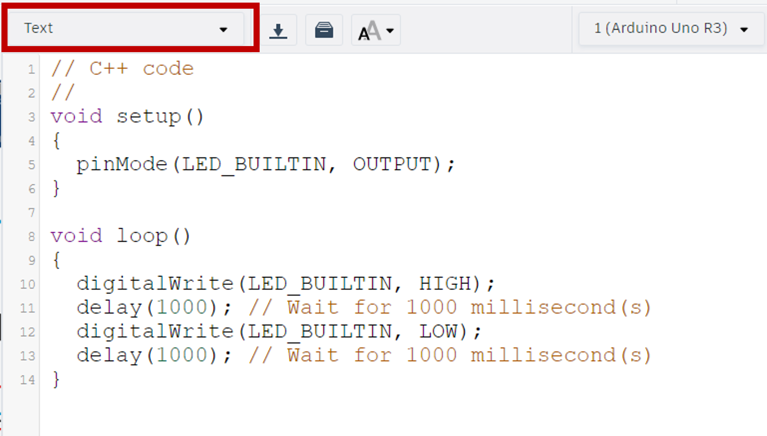
Y rhaglen a ddarperir yw rhaglen Arduino ddiofyn Tinkercad sy'n goleuo LED yr Arduino ac yn ei ddifodd.
Dilëwch gynnwys y void setup() a'r void loop() fel bod eich cod cychwyn yn edrych fel hyn:
    //C++ code
    //
    void setup ()
    {

    }

    void loop ()
    {

    }
void setup() (ar ddechrau).
pinMode() i ganfod pin sy'n cael ei ddefnyddio a gweld a yw'n INPUT neu'n OUTPUT.pinMode() mae angen i ni ychwanegu rhif y pin a'i fod yn OUTPUT.
Os ydych chi'n dal yn sownd, defnyddiwch y botwm ateb isod.
    //C++ code
    //
    void setup ()
    {
      pinMode(13, OUTPUT);
    }

    void loop ()
    {

    }
void loop() (dolen am byth) ysgrifennwch y cod i oleuo'r LED hwn a'i ddiffodd.
Awgrym: Bydd angen i chi ychwanegu delay() o 100ms rhwng newidiadau golau er mwyn eu gweld yn yr efelychydd.
digitalWrite() i ddweud wrth gydran ddigidol am droi ymlaen neu ddiffodd.digitalWrite() mae angen i ni gynnwys y pin rydym ni'n ei newid ac yna HIGH neu LOW.delay() yn gwneud i'r rhaglen aros am y cyfnod o amser a nodir y tu mewn i'r cromfachau - wedi'i fesur mewn milieiliadau.void loop() yn gweithio'r un fath â dolen am byth.Os ydych chi'n dal yn sownd, defnyddiwch y botwm ateb isod.
    //C++ code
    //
    void setup ()
    {
      pinMode(13, OUTPUT);
    }

    void loop ()
    {
      digitalWrite(13, HIGH);
      delay(100);
      digitalWrite(13, LOW);
      delay(100);
    }
Awgrym: Mae'r LDR/Photoresistor yn ddyfais mewnbwn analog.
void setup().pinMode() fel yr eglurir yn yr ymarferion Lefel Efydd.Os ydych chi'n dal yn sownd, defnyddiwch y botwm ateb isod.
    //C++ code
    //
    void setup ()
    {
      pinMode(13, OUTPUT);
      pinMode(A0, INPUT);
    }

    void loop ()
    {
      digitalWrite(13, HIGH);
      delay(100);
      digitalWrite(13, LOW);
      delay(100);
    }
Awgrym: Dangoswyd sut mae sefydlu'r monitor cyfresol yn y wers fideo.
Serial.begin() () y tu mewn i'r void setup().Os ydych chi'n dal yn sownd, defnyddiwch y botwm ateb isod.
    //C++ code
    //
    void setup ()
    {
      pinMode(13, OUTPUT);
      pinMode(A0, INPUT);
      Serial.begin(9600);
    }

    void loop ()
    {
      digitalWrite(13, HIGH);
      delay(100);
      digitalWrite(13, LOW);
      delay(100);
    }
Awgrym: Mae'r gwerthoedd hyn yn gyfanrifau (rhifau cyfan). Mae hyn yn golygu bod angen i ni ddweud wrth y rhaglen fod hwn yn newidyn gyda math int.
Pwysig: Mae'r lle y caiff newidyn ei greu yn y rhaglen yn penderfynu ble gellir ei ddefnyddio.
Ar gyfer y pwnc hwn, byddwn yn defnyddio Newidynnau Drwy'r Cyfan. Mae'r rhain yn newidynnau rydyn ni'n eu diffinio ar ddechrau rhaglen, cyn y void setup() hyd yn oed. Mae hyn yn golygu y gallwn wedyn eu defnyddio mewn unrhyw ran a phob rhan o'r rhaglen.
Pe byddech chi'n creu newidyn y tu mewn i ddolen/swyddogaeth, dim ond y tu mewn i'r un ddolen/swyddogaeth honno y byddai'n hygyrch ac nid yn unrhyw ran arall o'r rhaglen. Byddai hyn yn cael ei alw'n Newidyn Lleol. Cofiwch, mae hyn yn golygu y bydd y newidyn yn cael ei ail-greu bob tro y bydd y ddolen/swyddogaeth y mae wedi ei osod ynddi yn rhedeg.
Os ydych chi'n dal yn sownd, defnyddiwch y botwm ateb isod.
    //C++ code
    //
    int ldrValue = 0;

    void setup ()
    {
      pinMode(13, OUTPUT);
      pinMode(A0, INPUT);
      Serial.begin(9600);
    }

    void loop ()
    {
      digitalWrite(13, HIGH);
      delay(100);
      digitalWrite(13, LOW);
      delay(100);
    }
void loop(), gwnewch yn siŵr bod eich newidyn gwrthydd golau-ddibynnol newydd (LDR) yn cyfateb i ddarlleniad y synhwyrydd LDR. Yna bydd y rhaglen yn argraffu gwerth y newidyn hwn i'r monitor cyfresol.
Awgrym: Mae'r LDR yn fewnbwn analog ac mae wedi'i gysylltu â phin A0.
analogRead() gyda'r pin a nodir tu mewn i'w gromfachau.Serial.print() yn dweud wrth y rhaglen am argraffu beth bynnag sydd o fewn ei gromfachau ar linell newydd y monitor cyfresol.Os ydych chi'n dal yn sownd, defnyddiwch y botwm ateb isod.
    //C++ code
    //
    int ldrValue = 0;

    void setup ()
    {
      pinMode(13, OUTPUT);
      pinMode(A0, INPUT);
      Serial.begin(9600);
    }

    void loop ()
    {
      digitalWrite(13, HIGH);
      delay(100);
      digitalWrite(13, LOW);
      delay(100);
      ldrValue = analogRead(A0);
      Serial.println(ldrValue);
    }
Mae dadfygiwr wedi ei adeiladu i mewn i olygydd cod Tinkercad. Mae hyn yn rhoi gwybod i ni pan fydd gwall yn y cod a'r math o wall. Mae'n rhedeg bob tro y byddwn yn dechrau'r efelychiad. Yn yr ymarfer hwn byddwn yn cyflwyno gwallau i'n rhaglen er mwyn ein helpu i'w cyfateb i'r negeseuon gwall.
Newidiwch eich void setup() i gyd-fynd â phob un o'r enghreifftiau isod er mwyn gweld y neges gwall a gynhyrchir.
Awgrym: gall y rhifau ar ddechrau'r negeseuon gwall fod yn wahanol gan eu bod yn cyfeirio at rifau llinell yn y cod sy'n dibynnu ar eich bylchiad.
1. Colli '}':
2. Colli '{':
    void setup ()

      pinMode(13, OUTPUT);
      pinMode(A0, INPUT);
      Serial.begin(9600);
    }
3. Colli ';':
    void setup ()
    {
      pinMode(13, OUTPUT);
      pinMode(A0, INPUT)
      Serial.begin(9600);
    }
4. Colli '()':
    void setup
    {
      pinMode(13, OUTPUT);
      pinMode(A0, INPUT);
      Serial.begin(9600);
    }
5. Camgymeriad Sillafu:
    void setup ()
    {
      pinMoed(13, OUTPUT);
      pinMode(A0, INPUT);
      Serial.begin(9600);
    }
6. Colli ',':
    void setup ()
    {
      pinMode(13 OUTPUT);
      pinMode(A0, INPUT);
      Serial.begin(9600);
    }
    In function 'void setup()':
    13:1: error: a function-definition is not allowed here before '{' token
    20:1: error: expected '}' at end of input
    7:3: error: expected initializer before 'pinMode'
    8:10: error: expected constructor, destructor, or type conversion before '(' token
    9:3: error: 'Serial' does not name a type
    10:1: error: expected declaration before '}' token
      In function 'void setup()':
    9:3: error: expected ';' before 'Serial'
    5:6: error: variable or field 'setup' declared void
    7:22: error: expected '}' before ';' token
    8:10: error: expected constructor, destructor, or type conversion before '(' token
    9:3: error: 'Serial' does not name a type
    10:1: error: expected declaration before '}' token
      In function 'void setup()':
    7:3: error: 'pinMoed' was not declared in this scope
    7:3: note: suggested alternative: 'pinMode'
    1:0:
      In function 'void setup()':
    44:16: error: expected ')' before numeric constant


    7:14: note: in expansion of macro 'OUTPUT'
    7:20: error: too few arguments to function 'void pinMode(uint8_t, uint8_t)'
    1:0:
    134:6: note: declared here
Mae'r ymarferion hyn yn parhau i ddefnyddio'r rhaglen a ddatblygwyd yn Sesiwn Un.
Dylai pob dysgwr ddechrau ar lefel efydd a gweithio eu ffordd i fyny cyn belled ag y bo modd.
Cliciwch ar bennawd pob her i'w ehangu.
Awgrym: Gan ein bod yn dal i ddefnyddio'r LED, peidiwch â thynnu gosodiad pinMode.
Os ydych chi'n dal yn sownd, defnyddiwch y botwm ateb isod.
  //C++ code
  //
  int ldrValue = 0;

  void setup ()
  {
    pinMode(13, OUTPUT);
    pinMode(A0, INPUT);
    Serial.begin(9600);
  }

  void loop ()
  {
    ldrValue = analogRead(A0);
    Serial.println(ldrValue);
  }
Awgrym: Os gwnaethoch chi gwblhau'r ymarfer estyniad cyntaf yn llwyddiannus yn Sesiwn Un, cewch hepgor y cam hwn.
void setup().Os ydych chi'n dal yn sownd, defnyddiwch y botwm ateb isod.
  //C++ code
  //
  int blueLED = 13;
  int ldrValue = 0;

  void setup ()
  {
    pinMode(13, OUTPUT);
    pinMode(A0, INPUT);
    Serial.begin(9600);
  }

  void loop ()
  {
    ldrValue = analogRead(A0);
    Serial.println(ldrValue);
  }
Awgrym: Er ei bod yn ymddangos bod A0 yn gymysgedd o nodau a llythrennau, mae'n rhif pin ac felly caiff ei gydnabod fel cyfanrif.
void setup().Os ydych chi'n dal yn sownd, defnyddiwch y botwm ateb isod.
void setup().void setup() ac unwaith yn y void loop().Os ydych chi'n dal yn sownd, defnyddiwch y botwm ateb isod.
void loop() sy'n rhoi'r bwlb LED ymlaen pan fydd y darlleniad LDR yn llai na 160.
Awgrym: Os aethoch chi i'r afael â'r ymarferion estyniad yn Sesiwn Un, dim ond yr amod ar gyfer y datganiad-os mae angen i chi ei newid.
digitalWrite gyda gwerthoedd HIGH a LOW.Os ydych chi'n dal yn sownd, defnyddiwch y botwm ateb isod.
  //C++ code
  //
  int ldr = A0;
  int blueLED = 13;
  int ldrValue = 0;

  void setup ()
  {
    pinMode(blueLED, OUTPUT);
    pinMode(ldr, INPUT);
    Serial.begin(9600);
  }

  void loop ()
  {
    ldrValue = analogRead(ldr);
    Serial.println(ldrValue);
    if (ldrValue < 160)
    {
      digitalWrite(blueLED, HIGH);
    }
    else
    {
      digitalWrite(blueLED, LOW);
    }
  }
Awgrym: Enw'r llyfrgell/estyniad yw Servo.h
#include i ychwanegu llyfrgell/estyniad.void setup().#include hanner colon (;) ar y diwedd.Os ydych chi'n dal yn sownd, defnyddiwch y botwm ateb isod.
  //C++ code
  //

  #include <Servo.h>

  int ldr = A0;
  int blueLED = 13;
  int ldrValue = 0;

  void setup ()
  {
    pinMode(blueLED, OUTPUT);
    pinMode(ldr, INPUT);
    Serial.begin(9600);
  }

  void loop ()
  {
    ldrValue = analogRead(ldr);
    Serial.println(ldrValue);
    if (ldrValue < 160)
    {
      digitalWrite(blueLED, HIGH);
    }
    else
    {
      digitalWrite(blueLED, LOW);
    }
  }
Awgrym: Gall llyfrgelloedd ychwanegol fod â gwahanol ffyrdd o gynhyrchu newidynnau. Yn yr achos hwn, defnyddiwn y gorchymyn Servo variableName; i ychwanegu servo.
Os ydych chi'n dal yn sownd, defnyddiwch y botwm ateb isod.
  //C++ code
  //

  #include <Servo.h>
  Servo myServo;

  int ldr = A0;
  int blueLED = 13;
  int ldrValue = 0;

  void setup ()
  {
    pinMode(blueLED, OUTPUT);
    pinMode(ldr, INPUT);
    Serial.begin(9600);
  }

  void loop ()
  {
    ldrValue = analogRead(ldr);
    Serial.println(ldrValue);
    if (ldrValue < 160)
    {
      digitalWrite(blueLED, HIGH);
    }
    else
    {
      digitalWrite(blueLED, LOW);
    }
  }
void setup() i ddweud wrth y rhaglen pa bin mae myServo wedi'i gysylltu iddo.
Awgrym: Mae'r gorchymyn llyfrgell Servo ar gyfer adnabod pinnau yn wahanol eto. Bydd angen i chi ddefnyddio strwythur gorchymynservoName.attach(pin);
servoName.attach(pin); rhowch myServo yn lle servoName a servoPin yn lle'r pin.Os ydych chi'n dal yn sownd, defnyddiwch y botwm ateb isod.
  //C++ code
  //

  #include <Servo.h>
  Servo myServo;

  int servoPin = 12;
  int ldr = A0;
  int blueLED = 13;
  int ldrValue = 0;

  void setup ()
  {
    pinMode(blueLED, OUTPUT);
    pinMode(ldr, INPUT);
    Serial.begin(9600);
    myServo.attach(servoPin);
  }

  void loop ()
  {
    ldrValue = analogRead(ldr);
    Serial.println(ldrValue);
    if (ldrValue < 160)
    {
      digitalWrite(blueLED, HIGH);
    }
    else
    {
      digitalWrite(blueLED, LOW);
    }
  }
void loop(), ysgrifennwch raglen gan ddefnyddio cyfarwyddiadau myServo.write(angle); i wneud i'r servo symud rhwng onglau 0°, 90°, 180°, and back to 90°. Cynhwyswch un eiliad o saib ar ôl pob symudiad.
Awgrym: Mae cyfarwyddyd delay(); yn defnyddio milieiliadau ar gyfer y gwerth y tu mewn i'r cromfachau. 1000 milieiliadau = 1 eiliad.
Os ydych chi'n dal yn sownd, defnyddiwch y botwm ateb isod.
  //C++ code
  //

  #include <Servo.h>
  Servo myServo;

  int servoPin = 12;
  int ldr = A0;
  int blueLED = 13;
  int ldrValue = 0;

  void setup ()
  {
    pinMode(blueLED, OUTPUT);
    pinMode(ldr, INPUT);
    Serial.begin(9600);
    myServo.attach(servoPin);
  }

  void loop ()
  {
    ldrValue = analogRead(ldr);
    Serial.println(ldrValue);
    if (ldrValue < 160)
    {
      digitalWrite(blueLED, HIGH);
    }
    else
    {
      digitalWrite(blueLED, LOW);
    }
    myServo.write(0);
    delay(1000);
    myServo.write(90);
    delay(1000);
    myServo.write(180);
    delay(1000);
    myServo.write(90);
    delay(1000);
  }
Awgrym: Bydd angen i chi edrych ar y gylched i wybod pa bin yw hwn.
Os ydych chi'n dal yn sownd, defnyddiwch y botwm ateb isod.
  //C++ code
  //

  #include <Servo.h>
  Servo myServo;

  int piezo = A3;
  int servoPin = 12;
  int ldr = A0;
  int blueLED = 13;
  int ldrValue = 0;

  void setup ()
  {
    pinMode(blueLED, OUTPUT);
    pinMode(ldr, INPUT);
    Serial.begin(9600);
    myServo.attach(servoPin);
  }

  void loop ()
  {
    ldrValue = analogRead(ldr);
    Serial.println(ldrValue);
    if (ldrValue < 160)
    {
      digitalWrite(blueLED, HIGH);
    }
    else
    {
      digitalWrite(blueLED, LOW);
    }
    myServo.write(0);
    delay(1000);
    myServo.write(90);
    delay(1000);
    myServo.write(180);
    delay(1000);
    myServo.write(90);
    delay(1000);
  }
pinMode() ar gyfer y swnyn y tu mewn i'r void setup().
Awgrym: Bydd angen i chi ystyried a yw'r swnyn yn fewnbwn neu'n allbwn.
Os ydych chi'n dal yn sownd, defnyddiwch y botwm ateb isod.
  //C++ code
  //

  #include <Servo.h>
  Servo myServo;

  int piezo = A3;
  int servoPin = 12;
  int ldr = A0;
  int blueLED = 13;
  int ldrValue = 0;

  void setup ()
  {
    pinMode(blueLED, OUTPUT);
    pinMode(ldr, INPUT);
    Serial.begin(9600);
    myServo.attach(servoPin);
    pinMode(piezo, OUTPUT);
  }

  void loop ()
  {
    ldrValue = analogRead(ldr);
    Serial.println(ldrValue);
    if (ldrValue < 160)
    {
      digitalWrite(blueLED, HIGH);
    }
    else
    {
      digitalWrite(blueLED, LOW);
    }
    myServo.write(0);
    delay(1000);
    myServo.write(90);
    delay(1000);
    myServo.write(180);
    delay(1000);
    myServo.write(90);
    delay(1000);
  }
void loop() eich rhaglen.tone(pin, frequency, duration);void loop().Os ydych chi'n dal yn sownd, defnyddiwch y botwm ateb isod.
  //C++ code
  //

  #include <Servo.h>
  Servo myServo;

  int piezo = A3;
  int servoPin = 12;
  int ldr = A0;
  int blueLED = 13;
  int ldrValue = 0;

  void setup ()
  {
    pinMode(blueLED, OUTPUT);
    pinMode(ldr, INPUT);
    Serial.begin(9600);
    myServo.attach(servoPin);
    pinMode(piezo, OUTPUT);
  }

  void loop ()
  {
    ldrValue = analogRead(ldr);
    Serial.println(ldrValue);
    if (ldrValue < 160)
    {
      digitalWrite(blueLED, HIGH);
    }
    else
    {
      digitalWrite(blueLED, LOW);
    }
    myServo.write(0);
    delay(1000);
    myServo.write(90);
    delay(1000);
    myServo.write(180);
    delay(1000);
    myServo.write(90);
    delay(1000);
    if (ldrValue < 60)
    {
      tone(piezo, 65, 500);
    }
    else if (ldrValue < 100)
    {
      tone(piezo, 82, 500);
    }
    else if (ldrValue < 160)
    {
      tone(piezo, 98, 500);
    }
    else if (ldrValue < 220)
    {
      tone(piezo, 131, 500);
    }
    else if (ldrValue < 280)
    {
      tone(piezo, 165, 500);
    }
    else if (ldrValue < 340)
    {
      tone(piezo, 196, 500);
    }
    else if (ldrValue < 400)
    {
      tone(piezo, 262, 500);
    }
    else if (ldrValue < 460)
    {
      tone(piezo, 330, 500);
    }
    else if (ldrValue < 520)
    {
      tone(piezo, 392, 500);
    }
    else
    {
      tone(piezo, 523, 500);
    }
  }
Ar gyfer yr ymarferion hyn byddem yn argymell eich bod yn defnyddio copi o'ch rhaglen rhag ofn i bethau fynd o chwith.
Mapio: Fel gyda'r codio bloc blaenorol yn Makecode a Tinkercad, mae'n bosib mapio amrediad o werthoedd o fewnbynnau i allbynnau yn lle cael os-datganiadau mor hir.
Ar gyfer hyn mae angen i ni greu gwerth i gynnal y mapio:
int mappedVariable = map(inputValue, inputMin, inputMax, outputMin, outputMax);
Er enghraifft, os hoffem fapio amrediad potensiomedr (mewnbwn analog) i LED (allbwn analog), i wneud yr LED yn fwy disglair wrth i werth y potensiomedr gynyddu, mae angen y wybodaeth ganlynol arnom:
Byddai'r rhaglen yn edrych rhywbeth fel hyn:
Awgrym: Amrediad LDR yn yr efelychydd Tinkercad yw 6 i 679. Caiff ongl y servo fod yn unrhyw beth rhwng 0 a 180.
Ystod amlder y swnyn yw 31 i 4978.
Byddwn yn parhau â'r rhaglen a gynhyrchwyd yn Sesiwn Dau.
Dylai pob dysgwr ddechrau ar lefel efydd a gweithio eu ffordd i fyny cyn belled ag y bo modd.
Cliciwch ar bennawd pob her i'w ehangu.
Bydd yr ymarferion hyn yn dangos i chi sut i sefydlu swyddogaethau modur ar gyfer y robot hwn.
Newidyn o'r enw leftForwardPin sydd wedi'i osod i 10,
Newidyn o'r enw leftReversePin sydd wedi'i osod i 11,
Newidyn o'r enw rightForwardPin sydd wedi'i osod i 9,
Newidyn o'r enw rightReversePin sydd wedi'i osod i 6.
void setup() er mwyn i ni gael eu defnyddio drwy'r cyfan.Os ydych chi'n dal yn sownd, defnyddiwch y botwm ateb isod.
Dangosir y rhan o'r rhaglen a newidiwyd isod. Bydd y rhaglen lawn yn cael ei hychwanegu ar ddiwedd pob lefel.
pinMode(leftForwardPin, OUTPUT);Os ydych chi'n dal yn sownd, defnyddiwch y botwm ateb isod.
Dangosir y rhan o'r rhaglen a newidiwyd isod. Bydd y rhaglen lawn yn cael ei hychwanegu ar ddiwedd pob lefel.
  void setup ()
  {
    pinMode(leftForwardPin, OUTPUT);
    pinMode(leftReversePin, OUTPUT);
    pinMode(rightForwardPin, OUTPUT);
    pinMode(rightReversePin, OUTPUT);
    pinMode(blueLED, OUTPUT);
    pinMode(ldr, INPUT);
    Serial.begin(9600);
    myServo.attach(servoPin);
    pinMode(piezo, OUTPUT);
  }
Awgrym: Mae'r moduron a ddefnyddir yn y gylched hon yn ddyfeisiau digidol.
void setup(). Bydd hyn yn lleihau'r risg o gymysgu'r swyddogaethau newydd hyn yn ddamweiniol o fewn y rhaglen bresennol.
void functionName() { } gyda'r cyfarwyddiadau y tu mewn i'r cromfachau cyrliog.
digitalWrite(); ar gyfer pob newidyn modur.
digitalWrite(); bydd angen i chi gynnwys y newidyn a nodi a yw'n HIGH neu'n LOW.
  void forward()
  {
    digitalWrite(leftForwardPin, HIGH);
    digitalWrite(leftReversePin, LOW);
    digitalWrite(rightForwardPin, HIGH);
    digitalWrite(rightReversePin, LOW);
  }
Os ydych chi'n dal yn sownd, defnyddiwch y botwm ateb isod.
Dangosir y rhan o'r rhaglen a newidiwyd isod. Bydd y rhaglen lawn yn cael ei hychwanegu ar ddiwedd pob lefel.
  int ldrValue = 0;

  void robotForward()
  {
    digitalWrite(leftForwardPin, HIGH);
    digitalWrite(leftReversePin, LOW);
    digitalWrite(rightForwardPin, HIGH);
    digitalWrite(rightReversePin, LOW);
  }

  void robotReverse()
  {
    digitalWrite(leftForwardPin, LOW);
    digitalWrite(leftReversePin, HIGH);
    digitalWrite(rightForwardPin, LOW);
    digitalWrite(rightReversePin, HIGH);
  }

  void robotLeft()
  {
    digitalWrite(leftForwardPin, LOW);
    digitalWrite(leftReversePin, HIGH);
    digitalWrite(rightForwardPin, HIGH);
    digitalWrite(rightReversePin, LOW);
  }

  void robotRight()
  {
    digitalWrite(leftForwardPin, HIGH);
    digitalWrite(leftReversePin, LOW);
    digitalWrite(rightForwardPin, LOW);
    digitalWrite(rightReversePin, HIGH);
  }

  void robotStop()
  {
    digitalWrite(leftForwardPin, LOW);
    digitalWrite(leftReversePin, LOW);
    digitalWrite(rightForwardPin, LOW);
    digitalWrite(rightReversePin, LOW);
  }

  void setup ()
  //C++ code
  //

  #include <Servo.h>
  Servo myServo;

  int leftForwardPin = 10;
  int leftReversePin = 11;
  int rightForwardPin = 9;
  int rightReversePin = 6;
  int piezo = A3;
  int servoPin = 12;
  int ldr = A0;
  int blueLED = 13;
  int ldrValue = 0;

  void robotForward()
  {
    digitalWrite(leftForwardPin, HIGH);
    digitalWrite(leftReversePin, LOW);
    digitalWrite(rightForwardPin, HIGH);
    digitalWrite(rightReversePin, LOW);
  }

  void robotReverse()
  {
    digitalWrite(leftForwardPin, LOW);
    digitalWrite(leftReversePin, HIGH);
    digitalWrite(rightForwardPin, LOW);
    digitalWrite(rightReversePin, HIGH);
  }

  void robotLeft()
  {
    digitalWrite(leftForwardPin, LOW);
    digitalWrite(leftReversePin, HIGH);
    digitalWrite(rightForwardPin, HIGH);
    digitalWrite(rightReversePin, LOW);
  }

  void robotRight()
  {
    digitalWrite(leftForwardPin, HIGH);
    digitalWrite(leftReversePin, LOW);
    digitalWrite(rightForwardPin, LOW);
    digitalWrite(rightReversePin, HIGH);
  }

  void robotStop()
  {
    digitalWrite(leftForwardPin, LOW);
    digitalWrite(leftReversePin, LOW);
    digitalWrite(rightForwardPin, LOW);
    digitalWrite(rightReversePin, LOW);
  }

  void setup ()
  {
    pinMode(leftForwardPin, OUTPUT);
    pinMode(leftReversePin, OUTPUT);
    pinMode(rightForwardPin, OUTPUT);
    pinMode(rightReversePin, OUTPUT);
    pinMode(blueLED, OUTPUT);
    pinMode(ldr, INPUT);
    Serial.begin(9600);
    myServo.attach(servoPin);
    pinMode(piezo, OUTPUT);
  }

  void loop ()
  {
    ldrValue = analogRead(ldr);
    Serial.println(ldrValue);
    if (ldrValue < 160)
    {
      digitalWrite(blueLED, HIGH);
    }
    else
    {
      digitalWrite(blueLED, LOW);
    }
    myServo.write(0);
    delay(1000);
    myServo.write(90);
    delay(1000);
    myServo.write(180);
    delay(1000);
    myServo.write(90);
    delay(1000);
    if (ldrValue < 60)
    {
      tone(piezo, 65, 500);
    }
    else if (ldrValue < 100)
    {
      tone(piezo, 82, 500);
    }
    else if (ldrValue < 160)
    {
      tone(piezo, 98, 500);
    }
    else if (ldrValue < 220)
    {
      tone(piezo, 131, 500);
    }
    else if (ldrValue < 280)
    {
      tone(piezo, 165, 500);
    }
    else if (ldrValue < 340)
    {
      tone(piezo, 196, 500);
    }
    else if (ldrValue < 400)
    {
      tone(piezo, 262, 500);
    }
    else if (ldrValue < 460)
    {
      tone(piezo, 330, 500);
    }
    else if (ldrValue < 520)
    {
      tone(piezo, 392, 500);
    }
    else
    {
      tone(piezo, 523, 500);
    }
  }
void loop() sy'n galw ein swyddogaethau newydd pan fydd eu hangen. Rydym am i'n robot wneud y canlynol cyn symud ei servo:
Awgrym: Defnyddiwch y cyfarwyddyd delay(); ar gyfer yr amseroedd.
functionName(); gan ddisodli enw'r swyddogaeth i gyd-fynd â'r un rydych chi'n ei galw.
robotForward(), robotReverse(), robotLeft(), robotRight(), a robotStop(). Felly, gan ddefnyddio enwau'r swyddogaethau hyn, pe baem am i'r robot symud ymlaen am 5 eiliad ac yna stopio am 2 eiliad cyn symud yn ôl am 5 eiliad, byddem yn ysgrifennu:
  robotForward();
  delay(5000);
  robotStop();
  delay(2000);
  robotReverse();
  delay(5000);
  robotStop();
Os ydych chi'n dal yn sownd, defnyddiwch y botwm ateb isod.
Dangosir y rhan o'r rhaglen a newidiwyd isod. Bydd y rhaglen lawn yn cael ei hychwanegu ar ddiwedd pob lefel.
  void loop ()
  {
    ldrValue = analogRead(ldr);
    Serial.println(ldrValue);
    if (ldrValue < 160)
    {
      digitalWrite(blueLED, HIGH);
    }
    else
    {
      digitalWrite(blueLED, LOW);
    }

    robotForward();
    delay(1000);
    robotStop();
    delay(500);
    robotLeft();
    delay(500);
    robotRight();
    delay(1000);
    robotLeft();
    delay(500);
    robotStop();
    delay(500);
    robotReverse();
    delay(1000);
    robotStop();
    delay(1000);

    myServo.write(0);
    delay(1000);
    myServo.write(90);
    delay(1000);
    myServo.write(180);
    delay(1000);
    myServo.write(90);
    delay(1000);
  }
  //C++ code
  //

  #include <Servo.h>
  Servo myServo;

  int leftForwardPin = 10;
  int leftReversePin = 11;
  int rightForwardPin = 9;
  int rightReversePin = 6;
  int piezo = A3;
  int servoPin = 12;
  int ldr = A0;
  int blueLED = 13;
  int ldrValue = 0;

  void robotForward()
  {
    digitalWrite(leftForwardPin, HIGH);
    digitalWrite(leftReversePin, LOW);
    digitalWrite(rightForwardPin, HIGH);
    digitalWrite(rightReversePin, LOW);
  }

  void robotReverse()
  {
    digitalWrite(leftForwardPin, LOW);
    digitalWrite(leftReversePin, HIGH);
    digitalWrite(rightForwardPin, LOW);
    digitalWrite(rightReversePin, HIGH);
  }

  void robotLeft()
  {
    digitalWrite(leftForwardPin, LOW);
    digitalWrite(leftReversePin, HIGH);
    digitalWrite(rightForwardPin, HIGH);
    digitalWrite(rightReversePin, LOW);
  }

  void robotRight()
  {
    digitalWrite(leftForwardPin, HIGH);
    digitalWrite(leftReversePin, LOW);
    digitalWrite(rightForwardPin, LOW);
    digitalWrite(rightReversePin, HIGH);
  }

  void robotStop()
  {
    digitalWrite(leftForwardPin, LOW);
    digitalWrite(leftReversePin, LOW);
    digitalWrite(rightForwardPin, LOW);
    digitalWrite(rightReversePin, LOW);
  }

  void setup ()
  {
    pinMode(leftForwardPin, OUTPUT);
    pinMode(leftReversePin, OUTPUT);
    pinMode(rightForwardPin, OUTPUT);
    pinMode(rightReversePin, OUTPUT);
    pinMode(blueLED, OUTPUT);
    pinMode(ldr, INPUT);
    Serial.begin(9600);
    myServo.attach(servoPin);
    pinMode(piezo, OUTPUT);
  }

  void loop ()
  {
    ldrValue = analogRead(ldr);
    Serial.println(ldrValue);
    if (ldrValue < 160)
    {
      digitalWrite(blueLED, HIGH);
    }
    else
    {
      digitalWrite(blueLED, LOW);
    }

    robotForward();
    delay(1000);
    robotStop();
    delay(500);
    robotLeft();
    delay(500);
    robotRight();
    delay(1000);
    robotLeft();
    delay(500);
    robotStop();
    delay(500);
    robotReverse();
    delay(1000);
    robotStop();
    delay(1000);

    myServo.write(0);
    delay(1000);
    myServo.write(90);
    delay(1000);
    myServo.write(180);
    delay(1000);
    myServo.write(90);
    delay(1000);
    if (ldrValue < 60)
    {
      tone(piezo, 65, 500);
    }
    else if (ldrValue < 100)
    {
      tone(piezo, 82, 500);
    }
    else if (ldrValue < 160)
    {
      tone(piezo, 98, 500);
    }
    else if (ldrValue < 220)
    {
      tone(piezo, 131, 500);
    }
    else if (ldrValue < 280)
    {
      tone(piezo, 165, 500);
    }
    else if (ldrValue < 340)
    {
      tone(piezo, 196, 500);
    }
    else if (ldrValue < 400)
    {
      tone(piezo, 262, 500);
    }
    else if (ldrValue < 460)
    {
      tone(piezo, 330, 500);
    }
    else if (ldrValue < 520)
    {
      tone(piezo, 392, 500);
    }
    else
    {
      tone(piezo, 523, 500);
    }
  }
Rydym ni nawr yn mynd i sefydlu a rhaglennu'r synhwyrydd uwchsain.
Os ydych chi'n dal yn sownd, defnyddiwch y botwm ateb isod.
Dangosir y rhannau o'r rhaglen a newidiwyd isod. Bydd y rhaglen lawn yn cael ei hychwanegu ar ddiwedd pob lefel.
  int ultrasonicTrigger = 7;
  int ultrasonicEcho = 8;
  int leftForwardPin = 10;
  int leftReversePin = 11;
  int rightForwardPin = 9;
  int rightReversePin = 6;
  int piezo = A3;
  int servoPin = 12;
  int ldr = A0;
  int blueLED = 13;
  int ldrValue = 0;
  void setup ()
  {
    pinMode(ultrasonicTrigger, OUTPUT);
    pinMode(ultrasonicEcho, INPUT);
    pinMode(leftForwardPin, OUTPUT);
    pinMode(leftReversePin, OUTPUT);
    pinMode(rightForwardPin, OUTPUT);
    pinMode(rightReversePin, OUTPUT);
    pinMode(blueLED, OUTPUT);
    pinMode(ldr, INPUT);
    Serial.begin(9600);
    myServo.attach(servoPin);
    pinMode(piezo, OUTPUT);
  }
Pwysig: Mae gan y synhwyrydd uwchsain broses osod gymhleth nad oes angen i chi boeni am ei dysgu ar hyn o bryd. Yn lle hynny, gofynnwn i chi gopïo'r swyddogaeth gyfrifo isod yn ofalus i'ch rhaglen yn union ar ôl eich swyddogaethau modur ond cyn y void setup();.
  int readUltrasonic()
  {
    digitalWrite(ultrasonicTrigger,LOW); // Clear the signal
    delayMicroseconds(2);
    digitalWrite(ultrasonicTrigger, HIGH); // Send out new signal
    delayMicroseconds(10);
    digitalWrite(ultrasonicTrigger,LOW); // Stop sending signal

    unsigned long duration = pulseIn(ultrasonicEcho, HIGH);
    int distance = duration /2 /29;
    Serial.print(distance);
    Serial.print("cm");
    return distance;
  }
Mae'r swyddogaeth hon yn rhoi'r pellter i wrthrych mae'n ei synhwyro mewn centimetrau. Gallwn nawr ei alw yn ein rhaglen i helpu gyda gweddill yr ymarfer hwn.
Sylwer os gwelwch yn dda: Os ydych chi'n defnyddio enwau newidyn gwahanol i'r rhai a ddarperir yng ngham 1, ni fydd hyn yn gweithio.
Dangosir y rhan o'r rhaglen a newidiwyd isod. Bydd y rhaglen lawn yn cael ei hychwanegu ar ddiwedd pob lefel.
myServo.write(0);
delay(1000);
myServo.write(90);
delay(1000);
myServo.write(180);
delay(1000);
myServo.write(90);
delay(1000);
readUltrasonic(). Yna, ar ôl iddo symud i 90°, gosodwch y newidyn 'front' i alw'r un swyddogaeth. Ailadroddwch eto am 180° gyda newidyn 'right'. Nid oes angen darllen y pedwerydd symudiad gan ein bod eisoes wedi cymryd hwnnw.
Awgrym: Cofiwch, pwrpas y seibiau yw rhoi amser i'r servos orffen eu symudiadau felly dylid cymryd y darlleniadau ar ôl y saib ond cyn y symudiad nesaf.
myServo.write(0);
delay(1000);
left = readUltrasonic();
myServo.write(90);
delay(1000);
myServo.write(180);
delay(1000);
myServo.write(90);
delay(1000);
Os ydych chi'n dal yn sownd, defnyddiwch y botwm ateb isod.
Dangosir y rhan o'r rhaglen a newidiwyd isod. Bydd y rhaglen lawn yn cael ei hychwanegu ar ddiwedd pob lefel.
myServo.write(0);
delay(1000);
left = readUltrasonic();
myServo.write(90);
delay(1000);
front = readUltrasonic();
myServo.write(180);
delay(1000);
right = readUltrasonic();
myServo.write(90);
delay(1000);
Awgrym: Mae swyddogaeth readUltrasonic() yn rhoi pellter mewn centimedrau.
front < 100.Os ydych chi'n dal yn sownd, defnyddiwch y botwm ateb isod.
Dangosir y rhan o'r rhaglen a newidiwyd isod. Bydd y rhaglen lawn yn cael ei hychwanegu ar ddiwedd pob lefel.
void loop(), crëwch set o gyfarwyddiadau a fydd yn argraffu i'r monitor cyfresol p'un ai'r ochr dde ynteu'r chwith sydd fwyaf diogel i deithio iddi.
Awgrym: Bydd hyn yn gofyn am os-ddatganiad, arall-os datganiad, ac arall-datganiad. Defnyddir y datganiad arall i dangos pan fo'r ddau fesuriad yr un peth.
Serial.println("gair");Os ydych chi'n dal yn sownd, defnyddiwch y botwm ateb isod.
Dangosir y rhan o'r rhaglen a newidiwyd isod. Bydd y rhaglen lawn yn cael ei hychwanegu ar ddiwedd pob lefel.
myServo.write(0);
delay(1000);
left = readUltrasonic();
myServo.write(90);
delay(1000);
front = readUltrasonic();
myServo.write(180);
delay(1000);
right = readUltrasonic();
myServo.write(90);
delay(1000);
if (right > left)
{
Serial.println("right");
}
else if (left > right)
{
Serial.println("left");
}
else
{
Serial.println("no problem");
}
//C++ code
//
#include <Servo.h>
Servo myServo;
  int left = 0;
  int front = 0;
  int right = 0;
  int ultrasonicTrigger = 7;
  int ultrasonicEcho = 8;
  int leftForwardPin = 10;
  int leftReversePin = 11;
  int rightForwardPin = 9;
  int rightReversePin = 6;
  int piezo = A3;
  int servoPin = 12;
  int ldr = A0;
  int blueLED = 13;
  int ldrValue = 0;
void robotForward()
{
digitalWrite(leftForwardPin, HIGH);
digitalWrite(leftReversePin, LOW);
digitalWrite(rightForwardPin, HIGH);
digitalWrite(rightReversePin, LOW);
}
void robotReverse()
{
digitalWrite(leftForwardPin, LOW);
digitalWrite(leftReversePin, HIGH);
digitalWrite(rightForwardPin, LOW);
digitalWrite(rightReversePin, HIGH);
}
void robotLeft()
{
digitalWrite(leftForwardPin, LOW);
digitalWrite(leftReversePin, HIGH);
digitalWrite(rightForwardPin, HIGH);
digitalWrite(rightReversePin, LOW);
}
void robotRight()
{
digitalWrite(leftForwardPin, HIGH);
digitalWrite(leftReversePin, LOW);
digitalWrite(rightForwardPin, LOW);
digitalWrite(rightReversePin, HIGH);
}
void robotStop()
{
digitalWrite(leftForwardPin, LOW);
digitalWrite(leftReversePin, LOW);
digitalWrite(rightForwardPin, LOW);
digitalWrite(rightReversePin, LOW);
}
int readUltrasonic()
{
digitalWrite(ultrasonicTrigger,LOW); // Clear the signal
delayMicroseconds(2);
digitalWrite(ultrasonicTrigger, HIGH); // Send out new signal
delayMicroseconds(10);
digitalWrite(ultrasonicTrigger,LOW); // Stop sending signal
unsigned long duration = pulseIn(ultrasonicEcho, HIGH);
int distance = duration /2 /29;
Serial.print(distance);
Serial.print("cm");
return distance;
}
void setup ()
{
pinMode(ultrasonicTrigger, OUTPUT);
pinMode(ultrasonicEcho, INPUT);
pinMode(leftForwardPin, OUTPUT);
pinMode(leftReversePin, OUTPUT);
pinMode(rightForwardPin, OUTPUT);
pinMode(rightReversePin, OUTPUT);
pinMode(blueLED, OUTPUT);
pinMode(ldr, INPUT);
Serial.begin(9600);
myServo.attach(servoPin);
pinMode(piezo, OUTPUT);
}
void loop ()
{
ldrValue = analogRead(ldr);
Serial.println(ldrValue);
if (ldrValue < 160)
{
digitalWrite(blueLED, HIGH);
}
else
{
digitalWrite(blueLED, LOW);
}
if (front < 100)
{
robotStop();
}
else
{
robotForward();
delay(1000);
robotStop();
delay(500);
robotLeft();
delay(500);
robotRight();
delay(1000);
robotLeft();
delay(500);
robotStop();
delay(500);
robotReverse();
delay(1000);
robotStop();
delay(1000);
}
  myServo.write(0);
  delay(1000);
  left = readUltrasonic();
  myServo.write(90);
  delay(1000);
  front = readUltrasonic();
  myServo.write(180);
  delay(1000);
  right = readUltrasonic();
  myServo.write(90);
  delay(1000);
if (right > left)
{
Serial.println("right");
}
else if (left > right)
{
Serial.println("left");
}
else
{
Serial.println("no problem");
}
if (ldrValue < 60)
{
tone(piezo, 65, 500);
}
else if (ldrValue < 100)
{
tone(piezo, 82, 500);
}
else if (ldrValue < 160)
{
tone(piezo, 98, 500);
}
else if (ldrValue < 220)
{
tone(piezo, 131, 500);
}
else if (ldrValue < 280)
{
tone(piezo, 165, 500);
}
else if (ldrValue < 340)
{
tone(piezo, 196, 500);
}
else if (ldrValue < 400)
{
tone(piezo, 262, 500);
}
else if (ldrValue < 460)
{
tone(piezo, 330, 500);
}
else if (ldrValue < 520)
{
tone(piezo, 392, 500);
}
else
{
tone(piezo, 523, 500);
}
}
I gael her ychwanegol rhowch gynnig ar y canlynol mewn copi o'ch rhaglen.
Dilëwch y symudiadau presennol o'ch void loop() () ac ysgrifennwch raglen newydd sydd yn golygu bod y robot yn defnyddio ei servos a'i ddarlleniadau uwchsonig cyn penderfynu pa ffordd i symud. Cofiwch, mae ein symudiadau chwith a dde yn cynnwys troi yn y fan a'r lle, mae'n rhaid i chi wedyn yrru ymlaen er mwyn mynd y ffordd honno.
This session, we shall be using a different Tinkercad circuit to revise everything covered in this topic.
You will need to copy our Sensor Board circuit to use for these exercises.
This sensor board has several sensors and LEDS fitted and will allow us to replicate a series of different home devices.
All learners should start with the bronze level and work their way up as far as they can.
Click on each challenge heading to expand.
In this section, we shall be creating a program using the LDR/Photoresistor to control the brightness of the red LED.
Os ydych chi'n dal yn sownd, defnyddiwch y botwm ateb isod.
  //C++ code
  //

  int ldrPin = A5;
  int redLEDPin = 3;

  void setup ()
  {

  }

  void loop ()
  {

  }
pinMode(); for these two components.
pinMode(); instruction requires you to tell it (inside the brackets) the pin's value and whether it is an input or output.Os ydych chi'n dal yn sownd, defnyddiwch y botwm ateb isod.
  //C++ code
  //

  int ldrPin = A5;
  int redLEDPin = 3;

  void setup ()
  {
    pinMode(ldrPin, INPUT);
    pinMode(redLEDPin, OUTPUT);
  }

  void loop ()
  {

  }
void loop() write a program to store the LDR's value in a variable.
Awgrym: You will need to create a new integer type variable for this.
Os ydych chi'n dal yn sownd, defnyddiwch y botwm ateb isod.
Awgrym: Don't forget to include the necessary set-up instruction to use the serial monitor.
void setup() function you will need to add the Serial.begin(9600); instruction so the program knows to use the serial monitor.void loop() you will need to write the variable value to the serial monitor.Os ydych chi'n dal yn sownd, defnyddiwch y botwm ateb isod.
Os ydych chi'n dal yn sownd, defnyddiwch y botwm ateb isod.
The range of the LDR in the Tinkercad simulator is 6 - 679.
Mapping: As with the previous block coding in Makecode and Tinkercad, it is possible to map ranges of values from inputs to outputs instead of having such long if-statements.
For this we need to create a value to hold the mapping:
int mappedVariable = map(inputValue, inputMin, inputMax, outputMin, outputMax);
For example, if we wanted to map the range of a potentiometer (analog input) to an LED (analog output), making the LED brighter as the potentiometer value increases, we need the following information:
The program would look something like this:
map(inputValue, inputMin, inputMax, outputMin, outputMax); we know the inputValue is our reading from step 4, the inputMin is 6 as we discovered in step 5, and from the same step we also know that inputMax is 679. The output is an LED, which always has a range of 0 - 255.void loop().Os ydych chi'n dal yn sownd, defnyddiwch y botwm ateb isod.
 //C++ code
 //

 int ldrPin = A5;
 int redLEDPin = 3;
 int ldrReading = 0;
 int ldrMapValue = 0;

 void setup ()
 {
   pinMode(ldrPin, INPUT);
   pinMode(redLEDPin, OUTPUT);
   Serial.begin(9600);
 }

 void loop ()
 {
   ldrReading = analogRead(ldrPin);
   Serial.println(ldrReading);
   ldrMapValue = map(ldrReading, 6, 679, 0, 255);
 }
Os ydych chi'n dal yn sownd, defnyddiwch y botwm ateb isod.
  //C++ code
  //

  int ldrPin = A5;
  int redLEDPin = 3;
  int ldrReading = 0;
  int ldrMapValue = 0;

  void setup ()
  {
    pinMode(ldrPin, INPUT);
    pinMode(redLEDPin, OUTPUT);
    Serial.begin(9600);
  }

  void loop ()
  {
    ldrReading = analogRead(ldrPin);
    Serial.println(ldrReading);
    ldrMapValue = map(ldrReading, 6, 679, 0, 255);
    analogWrite(redLEDPin, ldrMapValue);
  }
Os ydych chi'n dal yn sownd, defnyddiwch y botwm ateb isod.
  //C++ code
  //

  int ldrPin = A5;
  int redLEDPin = 3;
  int ldrReading = 0;
  int ldrMapValue = 0;

  void setup ()
  {
    pinMode(ldrPin, INPUT);
    pinMode(redLEDPin, OUTPUT);
    Serial.begin(9600);
  }

  void loop ()
  {
    ldrReading = analogRead(ldrPin);
    Serial.println(ldrReading);
    ldrMapValue = map(ldrReading, 6, 679, 255, 0);
    analogWrite(redLEDPin, ldrMapValue);
  }
Continue using the program developed in the Lefel Efydd.
In this set of exercises, we shall be creating a simulation of a home heating system. For this, we will need to use the temperature sensor to collect readings, the potentiometer to set our preferred heating level, and the blue and green LEDs to indicate when it is too cold, at the correct temperature, and too hot.
Awgrym: There are four new components being added; the temperature sensor, the potentiometer, the blue LED, and the green LED.
Os ydych chi'n dal yn sownd, defnyddiwch y botwm ateb isod.
void setup() instructions for these components.
pinMode() for each component.Os ydych chi'n dal yn sownd, defnyddiwch y botwm ateb isod.
The section of the program altered is shown below. The full program will be added at the end of the level.
void setup ()
{
pinMode(ldrPin, INPUT);
pinMode(redLEDPin, OUTPUT);
Serial.begin(9600);
pinMode(tempPin, INPUT);
pinMode(potPin, INPUT);
pinMode(greenLEDPin, OUTPUT);
pinMode(blueLEDPin, OUTPUT);
}
Awgrym: You will need a new variable to store this value.
Serial.println() command in your void loop() to print the value of your new variable.void loop() runs.Os ydych chi'n dal yn sownd, defnyddiwch y botwm ateb isod.
The sections of the program altered is shown below. The full program will be added at the end of the level.
  //C++ code
  //

  int ldrPin = A5;
  int redLEDPin = 3;
  int ldrReading = 0;
  int ldrMapValue = 0;
  int tempPin = A4;
  int potPin = A3;
  int greenLEDPin = 5;
  int blueLEDPin = 6;
int tempReading = 0;
void loop ()
{
ldrReading = analogRead(ldrPin);
Serial.println(ldrReading);
ldrMapValue = map(ldrReading, 6, 679, 255, 0);
analogWrite(redLEDPin, ldrMapValue);
tempReading = analogRead(tempPin);
Serial.println(tempReading);
}
The range of the temperature sensor in this simulator is 20 - 358.
Awgrym: You will need a new variable to hold your converted temperature value.
Os ydych chi'n dal yn sownd, defnyddiwch y botwm ateb isod.
The sections of the program altered is shown below. The full program will be added at the end of the level.
//C++ code
//
int ldrPin = A5;
int redLEDPin = 3;
int ldrReading = 0;
int ldrMapValue = 0;
int tempPin = A4;
int potPin = A3;
int greenLEDPin = 5;
int blueLEDPin = 6;
int tempReading = 0;
int tempDegreesC = 0;
void loop ()
{
ldrReading = analogRead(ldrPin);
Serial.println(ldrReading);
ldrMapValue = map(ldrReading, 6, 679, 255, 0);
analogWrite(redLEDPin, ldrMapValue);
tempReading = analogRead(tempPin);
Serial.println(tempReading);
tempDegreesC = map(tempReading, 20, 358, -40, 125);
}
Awgrym: Don't forget to turn the LED off when the temperature drops back down.
digitalWrite() command, with the HIGH and LOW instructions.delay() instructions.Os ydych chi'n dal yn sownd, defnyddiwch y botwm ateb isod.
The section of the program altered is shown below. The full program will be added at the end of the level.
void loop ()
{
ldrReading = analogRead(ldrPin);
Serial.println(ldrReading);
ldrMapValue = map(ldrReading, 6, 679, 255, 0);
analogWrite(redLEDPin, ldrMapValue);
tempReading = analogRead(tempPin);
Serial.println(tempReading);
tempDegreesC = map(tempReading, 20, 358, -40, 125);
if (tempDegreesC > 50)
{
digitalWrite(greenLEDPin, HIGH);
delay(250);
digitalWrite(greenLEDPin, LOW);
delay(250);
}
else if (tempDegreesC > 20)
{
digitalWrite(greenLEDPin, HIGH);
}
else
{
digitalWrite(greenLEDPin, LOW);
}
}
Awgrym: This is using the same method as converting the temperature readings.
Serial.print("") which will print whatever is typed between the quotation marks inside the brackets.void loop() to give you chance to read the serial monitor before the program repeats.Os ydych chi'n dal yn sownd, defnyddiwch y botwm ateb isod.
The sections of the program altered is shown below. The full program will be added at the end of the level.
//C++ code
//
int ldrPin = A5;
int redLEDPin = 3;
int ldrReading = 0;
int ldrMapValue = 0;
int tempPin = A4;
int potPin = A3;
int greenLEDPin = 5;
int blueLEDPin = 6;
int tempReading = 0;
int tempDegreesC = 0;
int potReading = 0;
int potDegreesC = 0;
void loop ()
{
ldrReading = analogRead(ldrPin);
Serial.println(ldrReading);
ldrMapValue = map(ldrReading, 6, 679, 255, 0);
analogWrite(redLEDPin, ldrMapValue);
tempReading = analogRead(tempPin);
Serial.println(tempReading);
tempDegreesC = map(tempReading, 20, 358, -40, 125);
if (tempDegreesC > 50)
{
digitalWrite(greenLEDPin, HIGH);
delay(250);
digitalWrite(greenLEDPin, LOW);
delay(250);
}
else if (tempDegreesC > 20)
{
digitalWrite(greenLEDPin, HIGH);
}
else
{
digitalWrite(greenLEDPin, LOW);
}
potReading = analogRead(potPin);
Serial.println("Potentiometer reading: ");
Serial.println(potReading);
potDegreesC = map(potReading, 0, 1023, 5, 35);
Serial.println("Potentiometer in degrees: ");
Serial.println(potDegreesC);
delay(1000);
}
Awgrym: Imagine that this is turning on the heating at the same time.
Os ydych chi'n dal yn sownd, defnyddiwch y botwm ateb isod.
The section of the program altered is shown below. The full program will be added at the end of the level.
void loop ()
{
ldrReading = analogRead(ldrPin);
Serial.println(ldrReading);
ldrMapValue = map(ldrReading, 6, 679, 255, 0);
analogWrite(redLEDPin, ldrMapValue);
tempReading = analogRead(tempPin);
Serial.println(tempReading);
tempDegreesC = map(tempReading, 20, 358, -40, 125);
if (tempDegreesC > 50)
{
digitalWrite(greenLEDPin, HIGH);
delay(250);
digitalWrite(greenLEDPin, LOW);
delay(250);
}
else if (tempDegreesC > 20)
{
digitalWrite(greenLEDPin, HIGH);
}
else
{
digitalWrite(greenLEDPin, LOW);
}
potReading = analogRead(potPin);
Serial.println("Potentiometer reading: ");
Serial.println(potReading);
potDegreesC = map(potReading, 0, 1023, 5, 35);
Serial.println("Potentiometer in degrees: ");
Serial.println(potDegreesC);
if (tempDegreesC < potDegreesC)
{
digitalWrite(blueLEDPin, HIGH);
}
else
{
digitalWrite(blueLEDPin, LOW);
}
}
//C++ code
//
int ldrPin = A5;
int redLEDPin = 3;
int ldrReading = 0;
int ldrMapValue = 0;
int tempPin = A4;
int potPin = A3;
int greenLEDPin = 5;
int blueLEDPin = 6;
int tempReading = 0;
int tempDegreesC = 0;
int potReading = 0;
int potDegreesC = 0;
  void setup ()
  {
    pinMode(ldrPin, INPUT);
    pinMode(redLEDPin, OUTPUT);
    Serial.begin(9600);
    pinMode(tempPin, INPUT);
    pinMode(potPin, INPUT);
    pinMode(greenLEDPin, OUTPUT);
    pinMode(blueLEDPin, OUTPUT);
  }
void loop ()
{
ldrReading = analogRead(ldrPin);
Serial.println(ldrReading);
ldrMapValue = map(ldrReading, 6, 679, 255, 0);
analogWrite(redLEDPin, ldrMapValue);
tempReading = analogRead(tempPin);
Serial.println(tempReading);
tempDegreesC = map(tempReading, 20, 358, -40, 125);
if (tempDegreesC > 50)
{
digitalWrite(greenLEDPin, HIGH);
delay(250);
digitalWrite(greenLEDPin, LOW);
delay(250);
}
else if (tempDegreesC > 20)
{
digitalWrite(greenLEDPin, HIGH);
}
else
{
digitalWrite(greenLEDPin, LOW);
}
potReading = analogRead(potPin);
Serial.println("Potentiometer reading: ");
Serial.println(potReading);
potDegreesC = map(potReading, 0, 1023, 5, 35);
Serial.println("Potentiometer in degrees: ");
Serial.println(potDegreesC);
if (tempDegreesC < potDegreesC)
{
digitalWrite(blueLEDPin, HIGH);
}
else
{
digitalWrite(blueLEDPin, LOW);
}
}
Continuing with our program we shall now program a home security system with some of the other components.
Os ydych chi'n dal yn sownd, defnyddiwch y botwm ateb isod.
The sections of the program altered is shown below. The full program will be added at the end of the level.
 //C++ code
 //

 int ldrPin = A5;
 int redLEDPin = 3;
 int ldrReading = 0;
 int ldrMapValue = 0;
 int tempPin = A4;
 int potPin = A3;
 int greenLEDPin = 5;
 int blueLEDPin = 6;
 int tempReading = 0;
int tempDegreesC = 0;
int potReading = 0;
int potDegreesC = 0;
int pirPin = 4;
int bulbPin = 12;
void setup ()
{
pinMode(ldrPin, INPUT);
pinMode(redLEDPin, OUTPUT);
Serial.begin(9600);
pinMode(tempPin, INPUT);
pinMode(potPin, INPUT);
pinMode(greenLEDPin, OUTPUT);
pinMode(blueLEDPin, OUTPUT);
pinMode(pirPin, INPUT);
pinMode(bulbPin, OUTPUT);
}
New Variable Type: The PIR sensor is a digital input device which reads TRUE when it detects motion, and FALSE when it does not. When a variable is true or false, it is called a Boolean type variable.
So, when creating a variable to store a digital input value, we use bool instead of int.
void loop() set this new variable to read the PIR's digital input.
digitalRead() instruction.Os ydych chi'n dal yn sownd, defnyddiwch y botwm ateb isod.
The sections of the program altered is shown below. The full program will be added at the end of the level.
 //C++ code
 //

 int ldrPin = A5;
 int redLEDPin = 3;
 int ldrReading = 0;
 int ldrMapValue = 0;
 int tempPin = A4;
 int potPin = A3;
 int greenLEDPin = 5;
 int blueLEDPin = 6;
 int tempReading = 0;
 int tempDegreesC = 0;
int potReading = 0;
int potDegreesC = 0;
int pirPin = 4;
int bulbPin = 12;
bool pirReading = 0;
void loop ()
{
ldrReading = analogRead(ldrPin);
Serial.println(ldrReading);
ldrMapValue = map(ldrReading, 6, 679, 255, 0);
analogWrite(redLEDPin, ldrMapValue);
tempReading = analogRead(tempPin);
Serial.println(tempReading);
tempDegreesC = map(tempReading, 20, 358, -40, 125);
if (tempDegreesC > 50)
{
digitalWrite(greenLEDPin, HIGH);
delay(250);
digitalWrite(greenLEDPin, LOW);
delay(250);
}
else if (tempDegreesC > 20)
{
digitalWrite(greenLEDPin, HIGH);
}
else
{
digitalWrite(greenLEDPin, LOW);
}
potReading = analogRead(potPin);
Serial.println("Potentiometer reading: ");
Serial.println(potReading);
potDegreesC = map(potReading, 0, 1023, 5, 35);
Serial.println("Potentiometer in degrees: ");
Serial.println(potDegreesC);
if (tempDegreesC < potDegreesC)
{
digitalWrite(blueLEDPin, HIGH);
}
else
{
digitalWrite(blueLEDPin, LOW);
}
pirReading = digitalRead(pirPin);
}
Boolean conditions: The conditions of an if statement (or else if statement), are Boolean - they are either true or false. If it is true, then the program runs its contents. If it is not true (false) then it skips to the next section.
This means that when we create an if statement checking to see if a Boolean variable is true we can simply use if (booleanVariable) because the condition is already checking to see if it is true.
For example: Let's say we have a Boolean variable called 'active' that tells the program to program to turn on an LED connected to pin 3 when 'active' is true. Here is the resulting program:
bool active = 0;
void setup()
{
pinMode(3, OUTPUT);
}
void loop()
{
active = FALSE;
if (active)
{
digitalWrite(3, HIGH);
}
else
{
digitalWrite(3, LOW);
}
}
This program is checking to see if the Boolean value of active is true, which it is not, so the light will not turn on.
If you wanted to change the program to do the opposite, turning the LED on when 'active' is false, you have two options. You could simply switch the instructions around in the previous program, like this:
Alternatively, you could have changed the condition to false using an exclaimation mark (!) before the variable name, like this:
If you do write if(boolVariable = TRUE) or if(boolVariable = FALSE), it will still work. However, it demonstrates that the programmer does not fully understand how if-statements work.
Os ydych chi'n dal yn sownd, defnyddiwch y botwm ateb isod.
The section of the program altered is shown below. The full program will be added at the end of the level.
void loop ()
{
ldrReading = analogRead(ldrPin);
Serial.println(ldrReading);
ldrMapValue = map(ldrReading, 6, 679, 255, 0);
analogWrite(redLEDPin, ldrMapValue);
tempReading = analogRead(tempPin);
Serial.println(tempReading);
tempDegreesC = map(tempReading, 20, 358, -40, 125);
if (tempDegreesC > 50)
{
digitalWrite(greenLEDPin, HIGH);
delay(250);
digitalWrite(greenLEDPin, LOW);
delay(250);
}
else if (tempDegreesC > 20)
{
digitalWrite(greenLEDPin, HIGH);
}
else
{
digitalWrite(greenLEDPin, LOW);
}
potReading = analogRead(potPin);
Serial.println("Potentiometer reading: ");
Serial.println(potReading);
potDegreesC = map(potReading, 0, 1023, 5, 35);
Serial.println("Potentiometer in degrees: ");
Serial.println(potDegreesC);
if (tempDegreesC < potDegreesC)
{
digitalWrite(blueLEDPin, HIGH);
}
else
{
digitalWrite(blueLEDPin, LOW);
}
pirReading = digitalRead(pirPin);
if (pirReading)
{
digitalWrite(bulbPin, HIGH);
delay(5000);
digitalWrite(bulbPin, LOW);
}
}
You now have a working security light which activates whenever something moves nearby.
Awgrym: Some of these components need more than one variable.
Os ydych chi'n dal yn sownd, defnyddiwch y botwm ateb isod.
Here is an example of the new code that needs adding. Remember, your variable names may vary. The complete program is available at the end of this level.
void setup() for these new components.
Os ydych chi'n dal yn sownd, defnyddiwch y botwm ateb isod.
Here is an example of the new code that needs adding. Remember, your variable names may vary. The complete program is available at the end of this level.
pinMode(forcePin, INPUT);
pinMode(rgbRedLEDPin, OUTPUT);
pinMode(rgbGreenLEDPin, OUTPUT);
pinMode(rgbBlueLEDPin, OUTPUT);
pinMode(tiltPin, INPUT);
pinMode(ultraTrigPin, OUTPUT);
pinMode(ultraEchoPin, INPUT);
int readUltrasonic()
{
digitalWrite(ultrasonicTrigger,LOW); // Clear the signal
delayMicroseconds(2);
digitalWrite(ultrasonicTrigger, HIGH); // Send out new signal
delayMicroseconds(10);
digitalWrite(ultrasonicTrigger,LOW); // Stop sending signal
unsigned long duration = pulseIn(ultrasonicEcho, HIGH);
int distance = duration /2 /29;
Serial.print(distance);
Serial.print("cm");
return distance;
}
You will need to change the variables of ultrasonicTrigger and ultrasonicEcho in this code to match the variable names you created for the ultrasonic sensor's trigger and echo pins.
Awgrym: As this is a function, have it in your code after the variables, but before the void setup() section
We've re-written the code provided to match the variable names in our answer program.
int readUltrasonic()
{
digitalWrite(ultraTrigPin,LOW); // Clear the signal
delayMicroseconds(2);
digitalWrite(ultraTrigPin, HIGH); // Send out new signal
delayMicroseconds(10);
digitalWrite(ultraTrigPin,LOW); // Stop sending signal
unsigned long duration = pulseIn(ultraEchoPin, HIGH);
int distance = duration /2 /29;
Serial.print(distance);
Serial.print("cm");
return distance;
}
Here is an example of the new code that needs adding. Remember, your function name may be different. The complete program is available at the end of this level.
void alarmSystem()
{
}
void loop(), use the serial monitor to work out the range for the force sensor. Remember, you already have lots of values being printed, so include some text. You may also need to add a delay to slow the serial monitor printouts.void loop().Os ydych chi'n dal yn sownd, defnyddiwch y botwm ateb isod.
Here is an example of setting the necessary variables for this:
Here is the code needed to find the range of the force sensor. This needs to be removed after use.
forceReading = analogRead(forcePin);
Serial.println("Force Reading: ");
Serial.println(forceReading);
delay(1000);
alarmSystem(); //to test our new function's program.
Here is the code for our alarm system function:
forceReading = analogRead(forcePin);
forceMapRed = map (forceReading, 0, 466, 0, 255);
analogWrite(rgbRedLEDPin, forceMapRed);
Os ydych chi'n dal yn sownd, defnyddiwch y botwm ateb isod.
Here is an example of setting the necessary variables for this:
int ultraMapBlue = 0;
Here is the code needed to find the range of the force sensor. This needs to be removed after use.
Serial.println("Ultrasonic Distance:");
Serial.println(readUltrasonic());
delay(1000);
alarmSystem(); //to test our new function's program.
Here is the code for our alarm system function:
ultraMapBlue = map (readUltrasonic(), 2, 331, 255, 0);
analogWrite(rgbBlueLEDPin, ultraMapBlue);
Os ydych chi'n dal yn sownd, defnyddiwch y botwm ateb isod.
You will need to add a new variable for the tilt sensor reading.
bool tiltReading = 0;
The program you'll need to add to you alarm system function. Variable names may differ to your own.
Os ydych chi'n dal yn sownd, defnyddiwch y botwm ateb isod.
The alarm system function should now look like this:
void alarmSystem()
{
forceReading = analogRead(forcePin);
forceMapRed = map (forceReading, 0, 466, 0, 255);
analogWrite(rgbRedLEDPin, forceMapRed);
delay(250);
analogWrite(rgbRedLEDPin, 0);
ultraMapBlue = map (readUltrasonic(), 2, 331, 255, 0);
analogWrite(rgbBlueLEDPin, ultraMapBlue);
delay(250);
analogWrite(rgbBlueLEDPin, 0);
tiltReading = digitalRead(tiltPin);
if (tiltReading)
{
digitalWrite(rgbGreenLEDPin, HIGH);
}
else
{
digitalWrite(rgbGreenLEDPin, LOW);
}
delay(250);
digitalWrite(rgbGreenLEDPin, LOW);
}
void loop() during testing, we have yet to decide when it should be called. Create a new Boolean type variable called 'activate'. We shall use this to tell the program that the alarm system needs to run if activate is set to TRUE.
void loop() to test.Os ydych chi'n dal yn sownd, defnyddiwch y botwm ateb isod.
  //C++ code
  //

  int ldrPin = A5;
  int redLEDPin = 3;
  int ldrReading = 0;
  int ldrMapValue = 0;
  int tempPin = A4;
  int potPin = A3;
  int greenLEDPin = 5;
  int blueLEDPin = 6;
  int tempReading = 0;
  int tempDegreesC = 0;
  int potReading = 0;
  int potDegreesC = 0;
int pirPin = 4;
int bulbPin = 12;
bool pirReading = 0;
  int forcePin = A1;
  int rgbRedLEDPin = 9;
  int rgbGreenLEDPin = 10;
  int rgbBlueLEDPin = 11;
  int tiltPin = 2;
  int ultraTrigPin = 7;
  int ultraEchoPin = 8;
int forceReading = 0;
int forceMapRed = 0;
int ultraMapBlue = 0;
bool tiltReading = 0;
bool activate = 0;
int readUltrasonic()
{
digitalWrite(ultraTrigPin,LOW); // Clear the signal
delayMicroseconds(2);
digitalWrite(ultraTrigPin, HIGH); // Send out new signal
delayMicroseconds(10);
digitalWrite(ultraTrigPin,LOW); // Stop sending signal
unsigned long duration = pulseIn(ultraEchoPin, HIGH);
int distance = duration /2 /29;
Serial.print(distance);
Serial.print("cm");
return distance;
}
void alarmSystem()
{
forceReading = analogRead(forcePin);
forceMapRed = map (forceReading, 0, 466, 0, 255);
analogWrite(rgbRedLEDPin, forceMapRed);
delay(250);
analogWrite(rgbRedLEDPin, 0);
ultraMapBlue = map (readUltrasonic(), 2, 331, 255, 0);
analogWrite(rgbBlueLEDPin, ultraMapBlue);
delay(250);
analogWrite(rgbBlueLEDPin, 0);
tiltReading = digitalRead(tiltPin);
if (tiltReading)
{
digitalWrite(rgbGreenLEDPin, HIGH);
}
else
{
digitalWrite(rgbGreenLEDPin, LOW);
}
delay(250);
digitalWrite(rgbGreenLEDPin, LOW);
}
void setup ()
{
pinMode(ldrPin, INPUT);
pinMode(redLEDPin, OUTPUT);
Serial.begin(9600);
pinMode(tempPin, INPUT);
pinMode(potPin, INPUT);
pinMode(greenLEDPin, OUTPUT);
pinMode(blueLEDPin, OUTPUT);
pinMode(pirPin, INPUT);
pinMode(bulbPin, OUTPUT);
  pinMode(forcePin, INPUT);
  pinMode(rgbRedLEDPin, OUTPUT);
  pinMode(rgbGreenLEDPin, OUTPUT);
  pinMode(rgbBlueLEDPin, OUTPUT);
  pinMode(tiltPin, INPUT);
  pinMode(ultraTrigPin, OUTPUT);
  pinMode(ultraEchoPin, INPUT);
}
void loop ()
{
ldrReading = analogRead(ldrPin);
Serial.println(ldrReading);
ldrMapValue = map(ldrReading, 6, 679, 255, 0);
analogWrite(redLEDPin, ldrMapValue);
tempReading = analogRead(tempPin);
Serial.println(tempReading);
tempDegreesC = map(tempReading, 20, 358, -40, 125);
if (tempDegreesC > 50)
{
digitalWrite(greenLEDPin, HIGH);
delay(250);
digitalWrite(greenLEDPin, LOW);
delay(250);
}
else if (tempDegreesC > 20)
{
digitalWrite(greenLEDPin, HIGH);
}
else
{
digitalWrite(greenLEDPin, LOW);
}
potReading = analogRead(potPin);
Serial.println("Potentiometer reading: ");
Serial.println(potReading);
potDegreesC = map(potReading, 0, 1023, 5, 35);
Serial.println("Potentiometer in degrees: ");
Serial.println(potDegreesC);
if (tempDegreesC < potDegreesC)
{
digitalWrite(blueLEDPin, HIGH);
}
else
{
digitalWrite(blueLEDPin, LOW);
}
pirReading = digitalRead(pirPin);
if (pirReading)
{
digitalWrite(bulbPin, HIGH);
delay(5000);
digitalWrite(bulbPin, LOW);
}
  activate = 1;
  if (activate)
  {
    alarmSystem();
  }
}
Should you wish to continue working with this circuit and program, here are some additional ideas for you.