Aberystwyth University's Electronics Online Workshop Series
We have adapted the material created for our Robotics Club for anyone to work through at home or in school.
Each of the below sessions include a video lesson from one of our staff and a set of exercises to assess your understanding. As this page is for independent learners, answers are included.
Please select a session heading to get started.
Video Lesson:
Using Tinkercad:
Tinkercad is a free in-browser software we can use to create, program, and simulate circuits. It also has classroom options for teachers - see our Educators Guide to Tinkercad.
To use the software, you will need to create an account or log-in with accepted alternatives (Google, Microsoft, Apple, or Facebook).
Once logged in, select designs from the left-hand menu. Click on new and select circuit to create a new file. Alternatively, you can scroll down your designs page to find previous circuit files you've created. Tinkercad autosaves your work after every change.
Exercises:
We have created three levels (bronze, silver, and gold) of challenge for learners to start investigating and creating circuits in Tinkercad.
All learners should start with the bronze level and work their way up as far as they can.
Click on each challenge heading to expand.
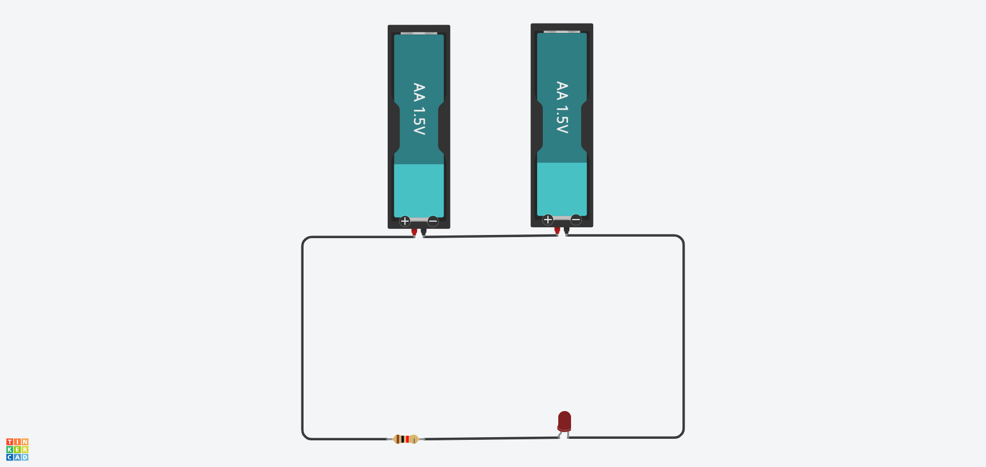
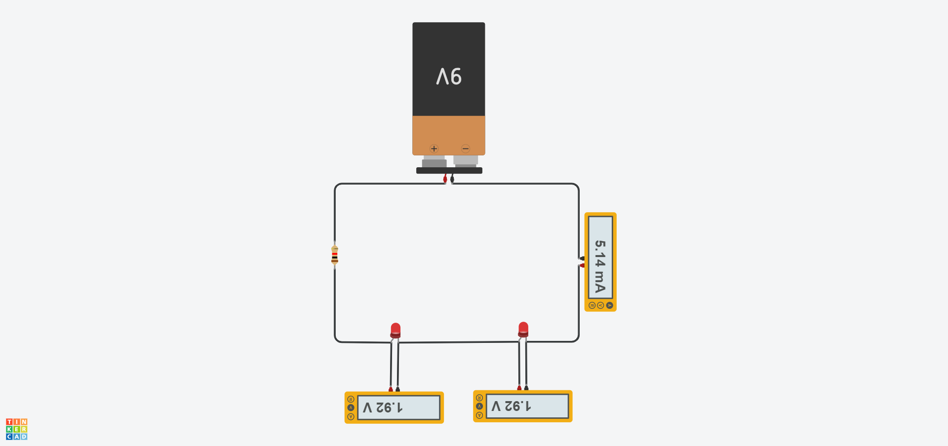
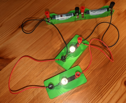
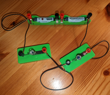
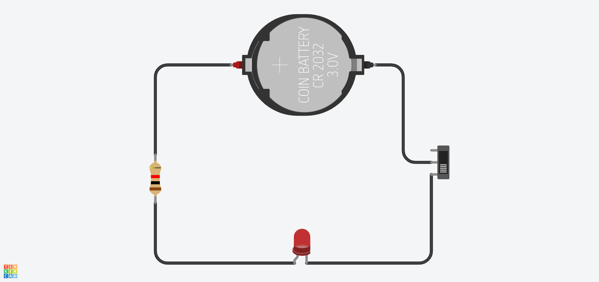
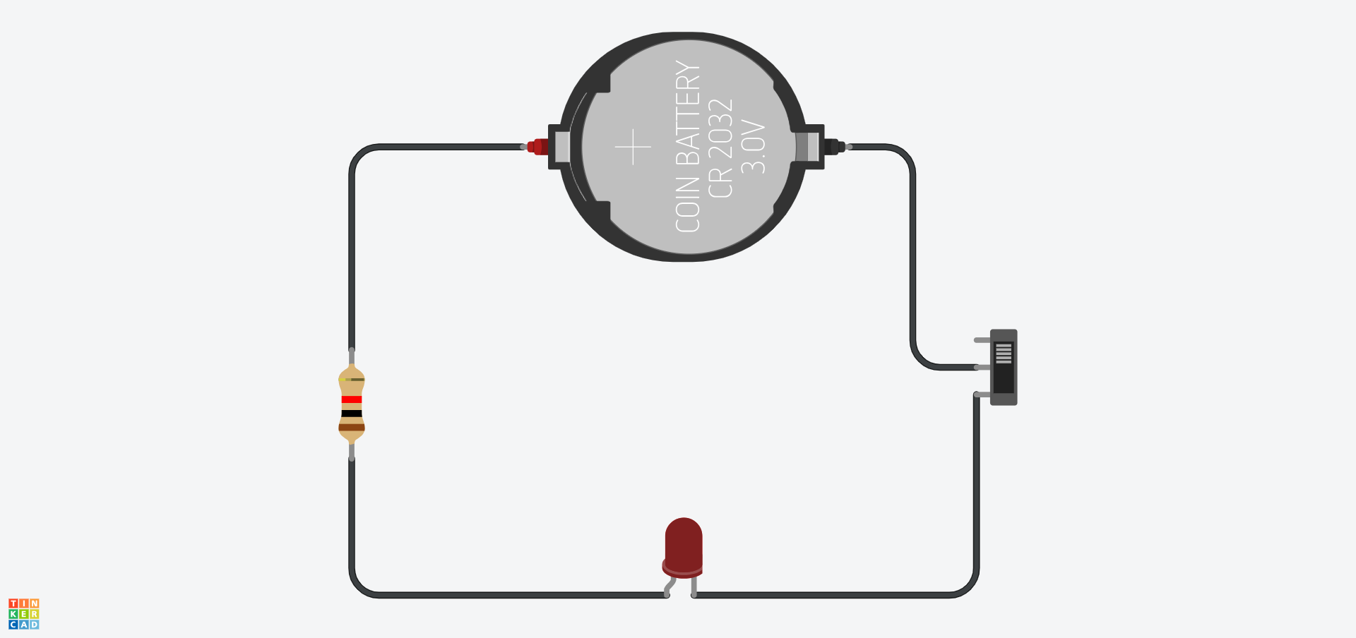
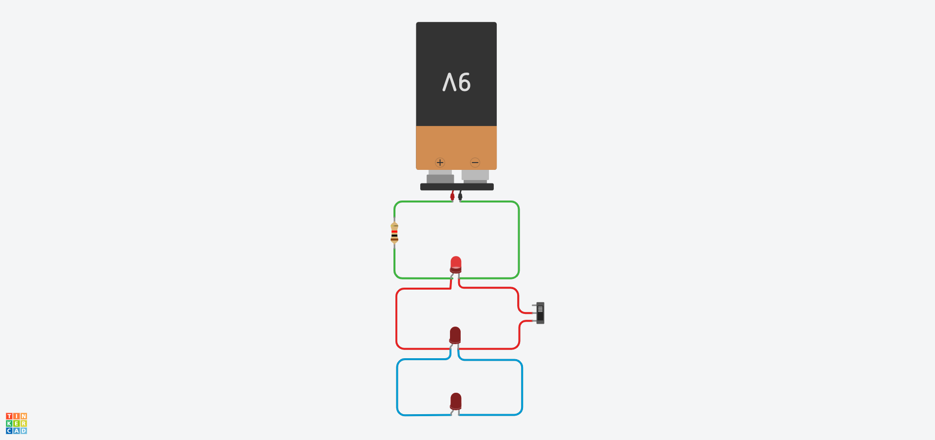
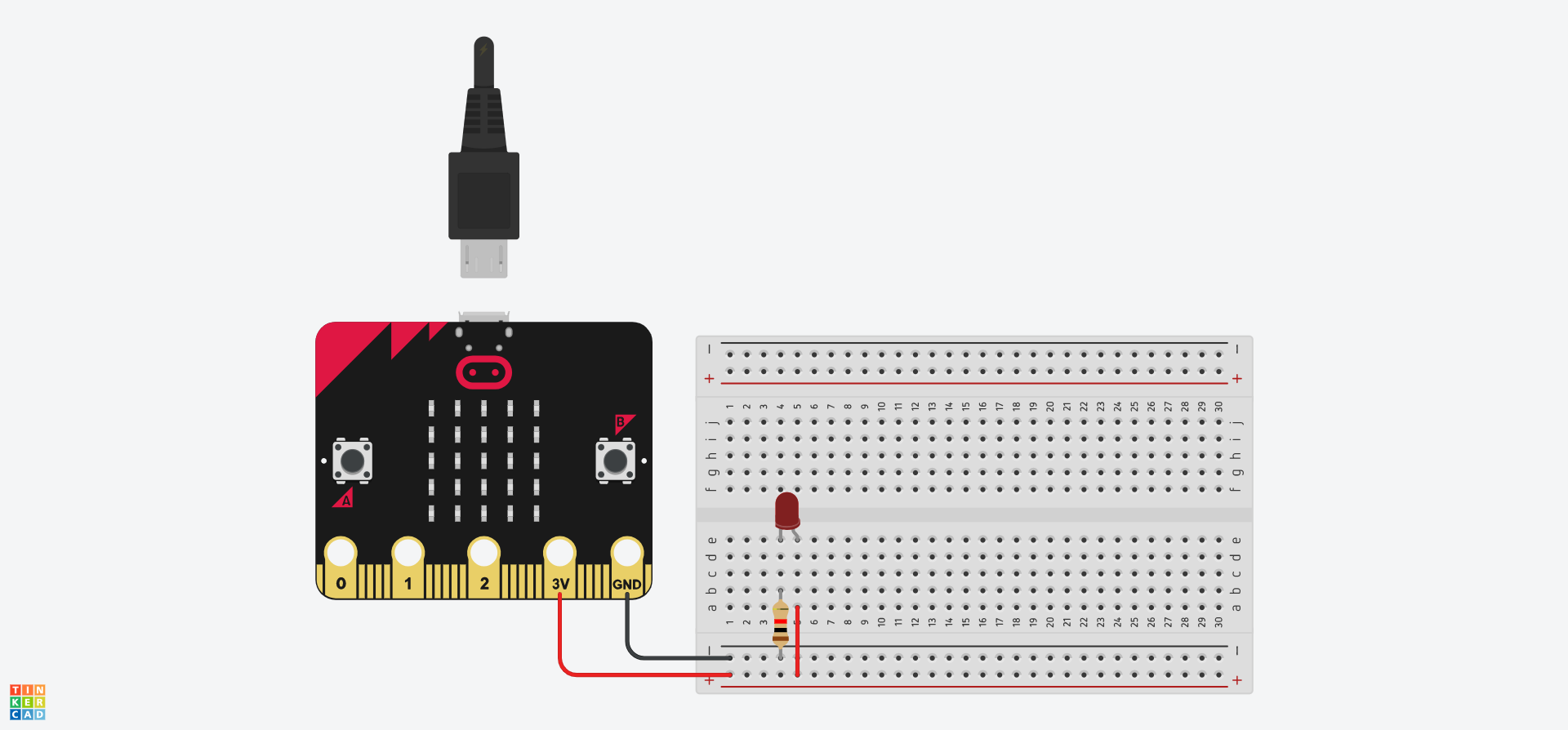
Recreate this circuit:
AA batteries are 1.5V power supplies and this circuit asks for two.
Remember, negative connects to positive.
The cathode is the positive terminal on an LED.
A resistor can be connected either way round - it does not have a negative or positive terminal.
If you are still stuck, use the answer button below.
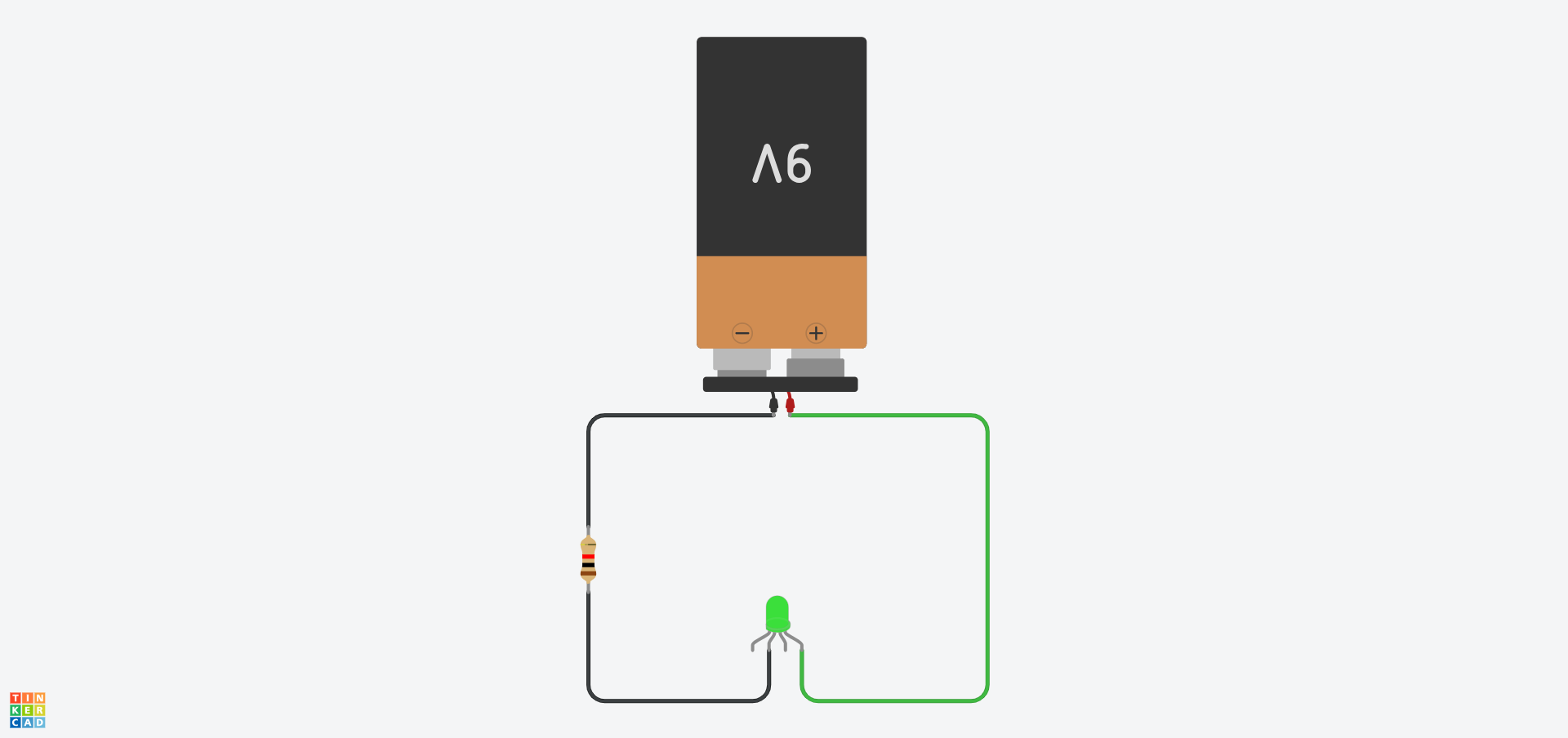
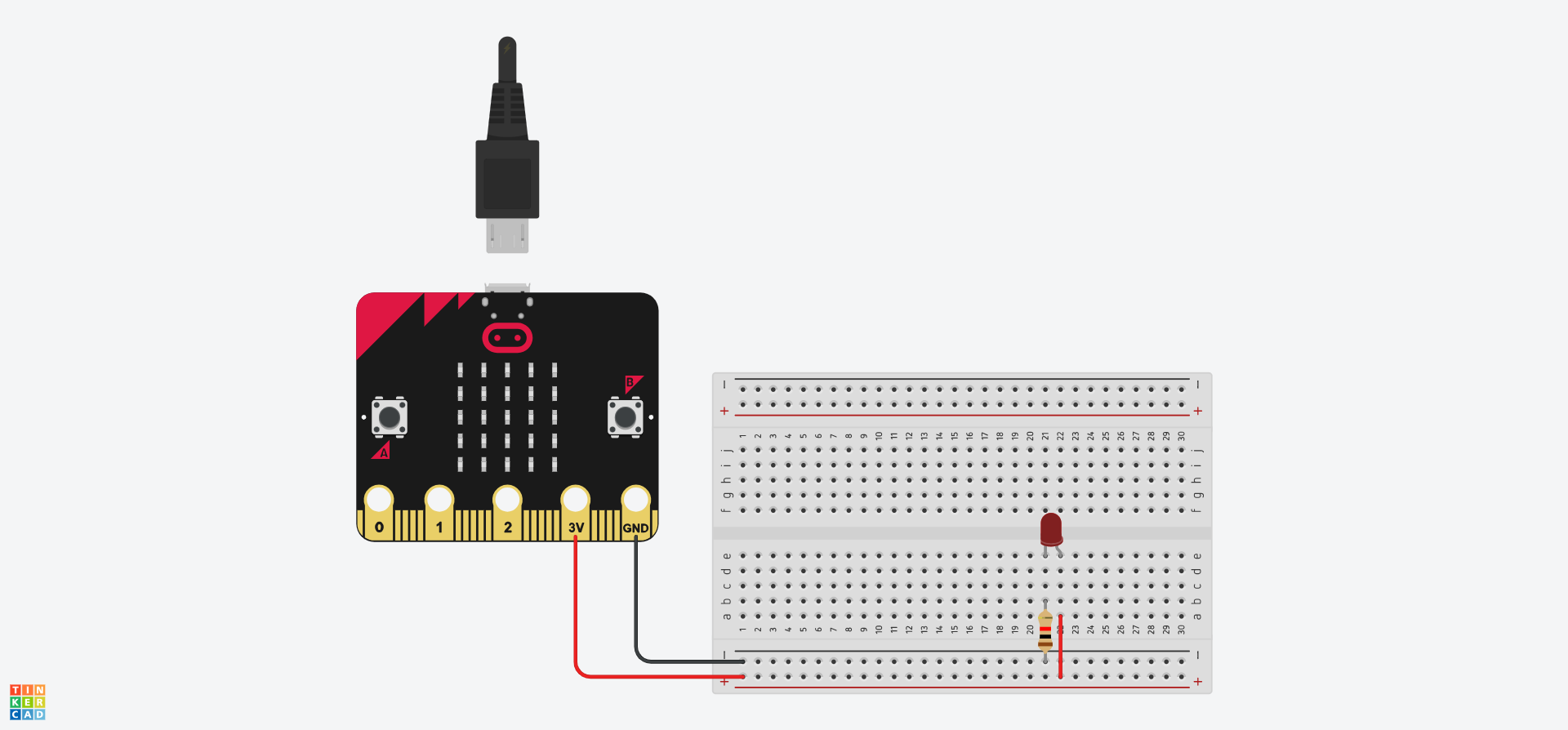
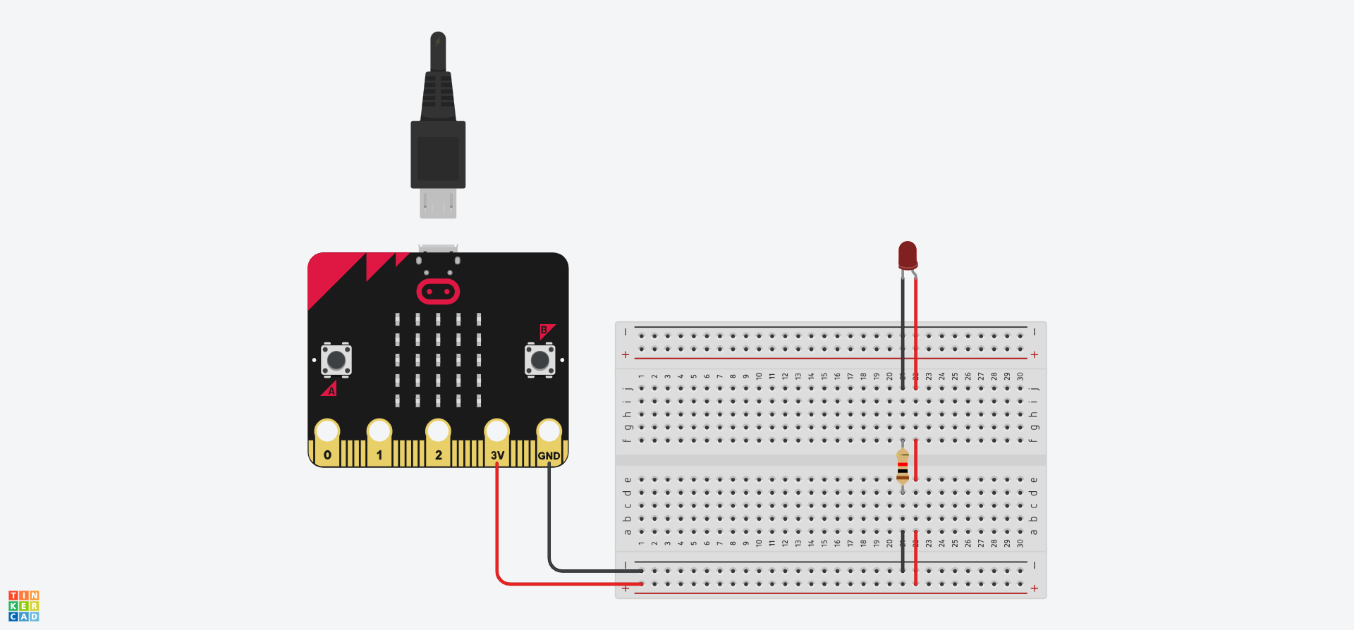
Create a new circuit file in Tinkercad (to return to the designs page click on the Tinkercad logo in the top left corner).
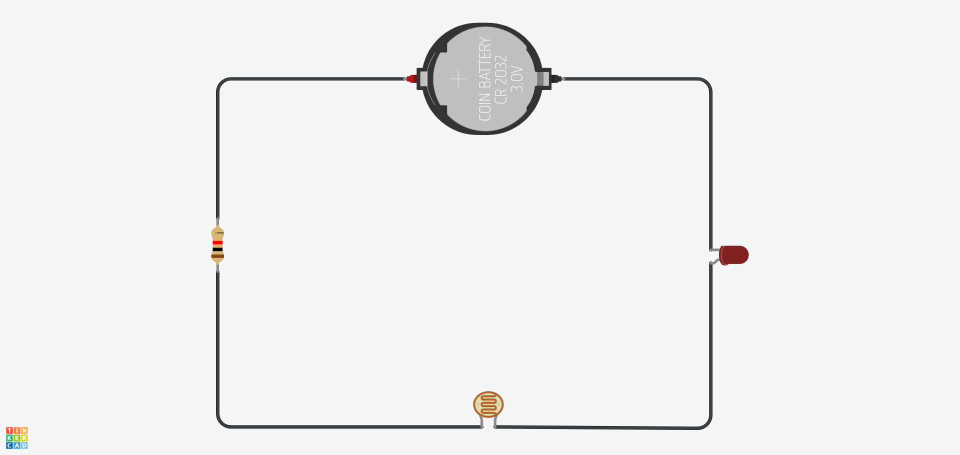
Recreate this circuit:
Tip: This includes an LDR (Light Dependent Resistor) which is called a 'photoresistor' in Tinkercad.
The button (round) battery is 3V, or you could use 2 AA batteries.
The LDR is a type of resistor, so it doesn't matter which way round it is wired.
If you are still stuck, use the answer button below.
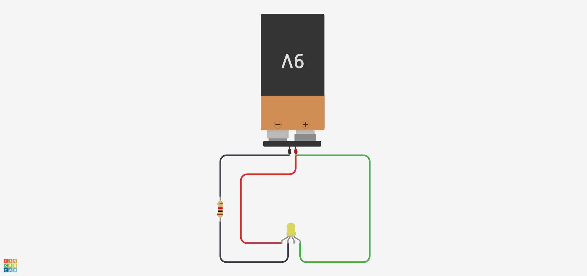
Start the simulator and click on the LDR/photoresistor. This will give you a light level scale you can adjust. See what happens to the LED when the light level is increased and decreased.
You can click and slide the light level. Moving it to the right increases the light level.
Create a new circuit file on Tinkercad for this exercise.
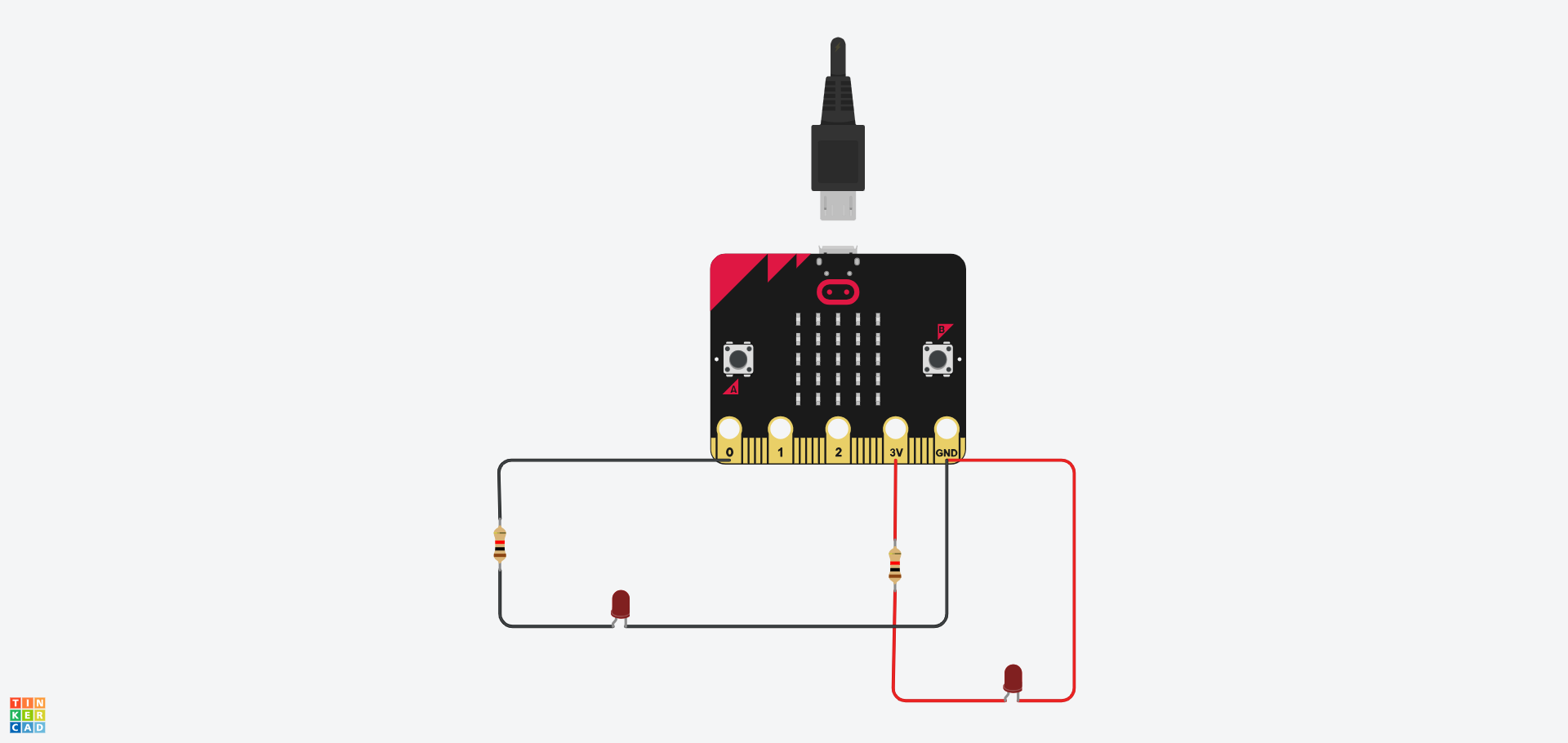
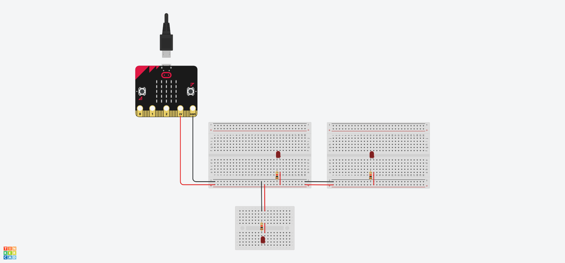
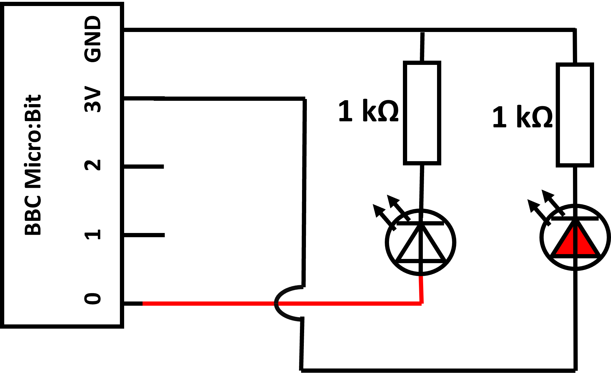
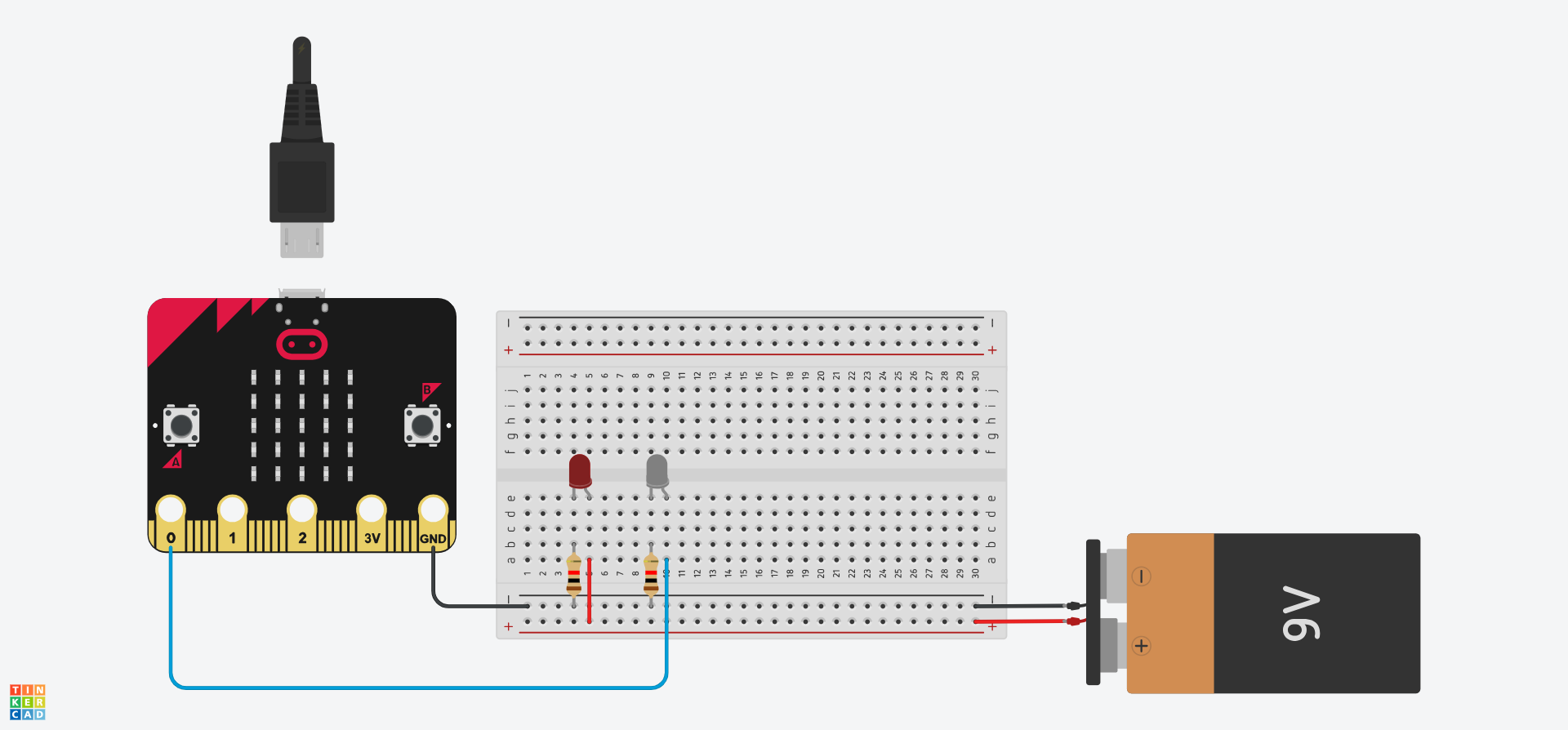
Recreate this circuit:
Tip: The arch where the wires cross show they pass over each other instead of connecting.
Tip: The GND pin on the Micro:Bit is the negative terminal.
The Micro:Bit replaces the need for a battery in this circuit. The power required (3V) is provided by the cable plugged into it.
You can use different coloured wires for the separate loops.
If you are still stuck, use the answer button below.
When you start the simulator, only one LED lights up. This is because the 3V pin acts like the positive end of a battery whilst the GND pin acts like the negative. This means anything connected to these two pins in a circuit will receive power. The other LED is attached to a numbered pin - these are programmable pins and without a program they will not provide power.
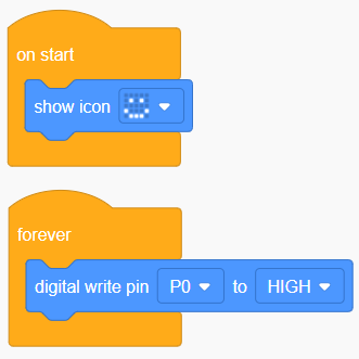
Write a program so both lights are turned on and stay on.
Tip: You can open the coding panel using the code button next to the start simulator button. Remember to stop the simulation first - you cannot edit the program whilst it is running.
You can use the 'digital write pin' block to set an LED on ('HIGH') or off ('LOW').
You could instead use an 'write analog pin' block to set the brightness (0 is off, 255 is maximum brightness).
If you are still stuck, use the answer button below.
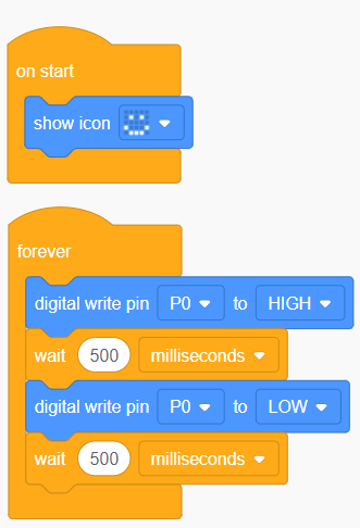
Change the program so the LED connected to pin 0 flashes on and off every 500ms.
The 'wait' block default measurement is seconds. You can change this to milliseconds inside the block or convert the value.
Remember, you will need a wait block after each change of the pin's value.
If you are still stuck, use the answer button below.
Create a new circuit file on Tinkercad for this exercise.
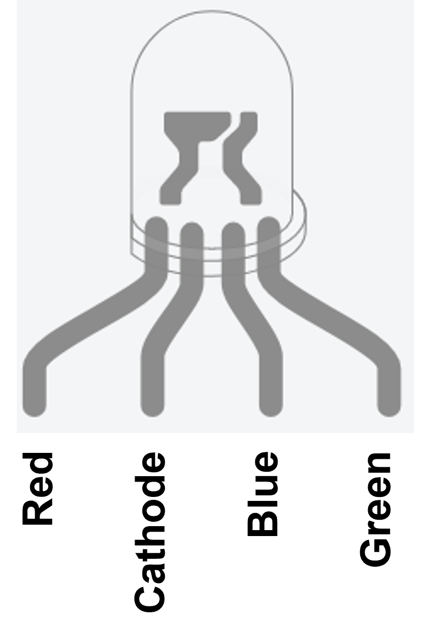
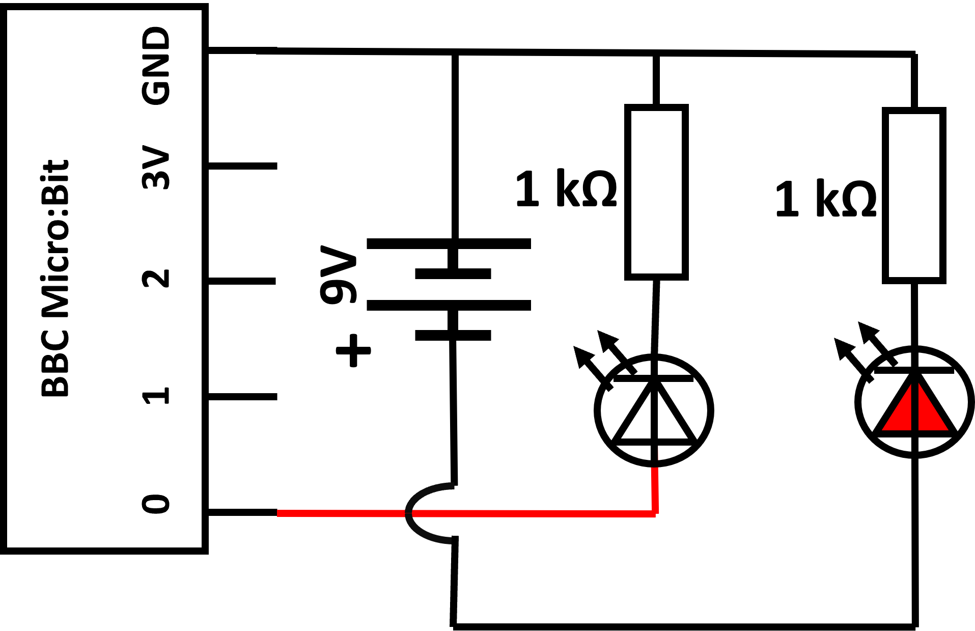
New Component: For this exercise you will be using an RGB LED. This is a LED light that can be programmed to light up in a variety of different colours. This component has 4 connection pins as labelled in the below image.
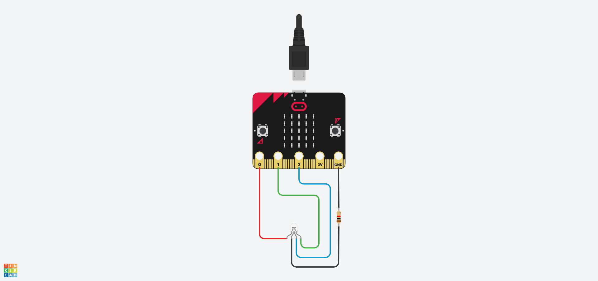
Create a circuit containing a BBC Micro:Bit, a resistor (1kΩ) and a RGB LED.
Tip: Each colour pin will need to be connected to a different programmable pin on the Micro:Bit.
The cathode is the positive terminal on the RGB LED.
The resistor will need to go between the cathode of the RGB LED and the GND pin of the Micro:Bit.
Use different coloured wires for each pin to help.
If you are still stuck, use the answer button below.
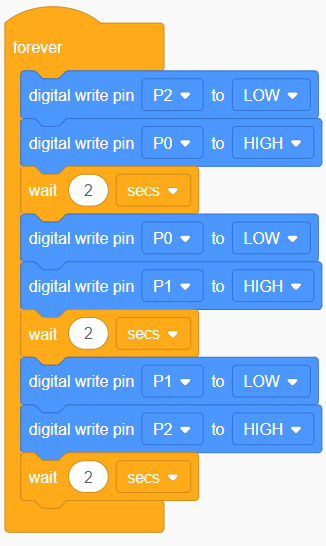
Program your circuit so the light changes colour every 2 seconds, repeating this sequence: red, green, blue.
For this, we can use the 'digital write pin' blocks.
Don't forget to turn off a colour before showing the next.
If you are still stuck, use the answer button below.
Be aware, the Micro:Bit pins used by each colour may be different for your circuit.
Change your program so the light changes colour every 2 seconds, repeating this sequence: red, magenta, blue, cyan, green, yellow, white.
Tip: Magenta, cyan, and yellow light are each made up from mixing two colours from red, blue, and green. For more information about mixing light colours please see our Science of Colour activity.
See what happens if you have red and blue both set to 'HIGH' at the same time. Repeat with blue and green, then green and red.
White light is created by having all the pins set to 'HIGH'.
Don't forget to turn off the colours not needed.
If you are still stuck, use the answer button below.
Be aware, the Micro:Bit pins used by each colour may be different for your circuit.
Video Lesson:
Exercises:
This session looks at creating circuits in Tinkercad to investigate current and voltage.
All learners should start with the bronze level and work their way up as far as they can.
Click on each challenge heading to expand.
New Information:
A circuit made up of a single loop of wires and components is called a Series Circuit.
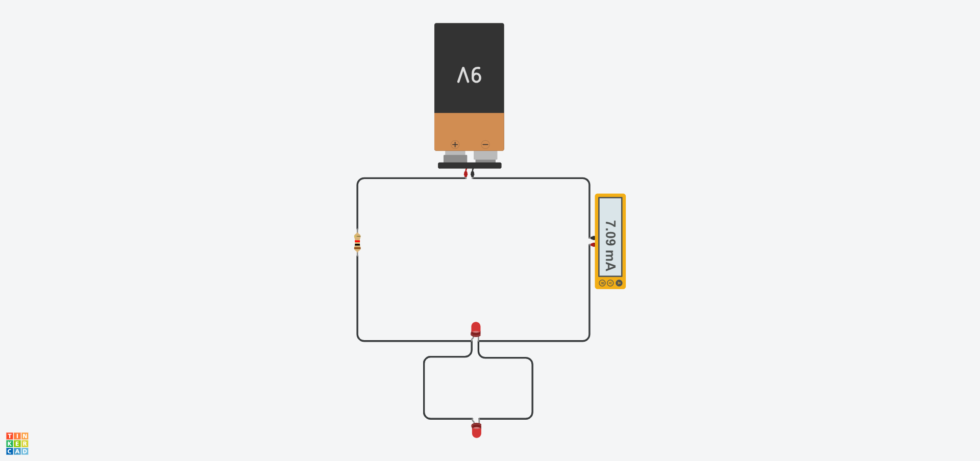
Recreate this series circuit:
Tinkercad does not include an Ammeter, instead it has a multi-meter that can be used to measure current in the same way.
If you are still stuck, use the answer button below.
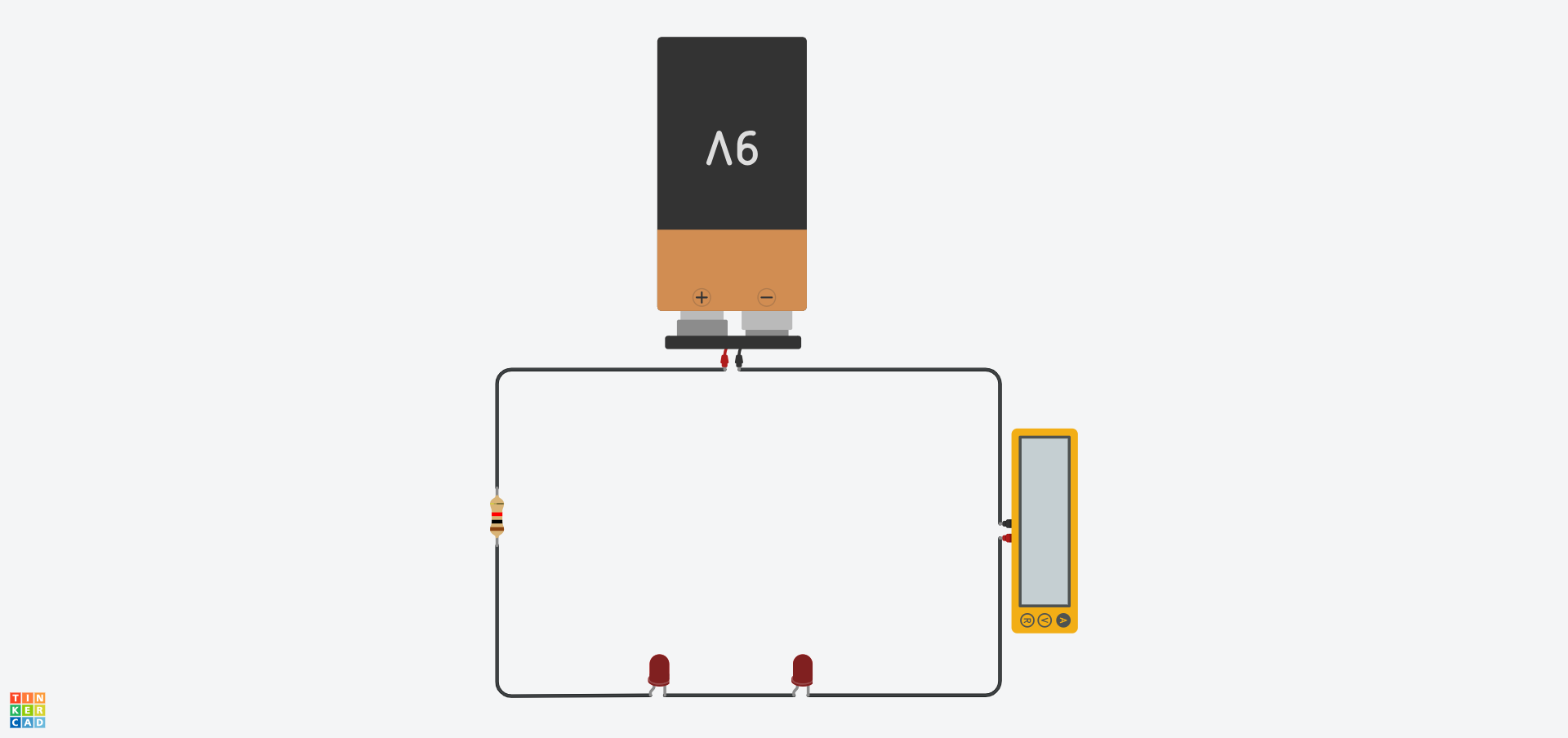
What is the current in this circuit?
If the value is negative, the meter wires are the wrong way round.
Check the mode of the multi-meter is set to Amperage.
The leds should all be lit, if not, check your wiring.
If you are still stuck, use the answer button below.
You should have a value on the meter of 5.14mA. This means the current in your circuit is 5.14 milli-Amps, or 0.00514 Amps.
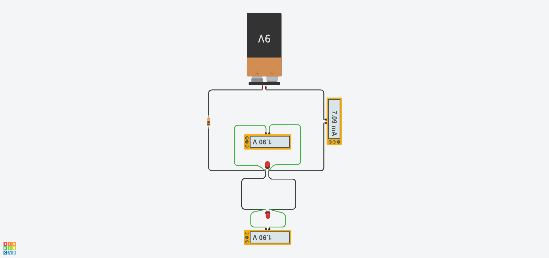
What voltage does each LED use?
Tip: You will need to add two more multi-meters to the circuit.
To measure the voltage for each LED, you will need to add a multi-meter to each.
Here is the new circuit diagram for what you need to add.
Again, if you have a negative reading it means the multi-meter wires are the wrong way round.
If you are still stuck, use the answer button below.
New Information:
You can also have Parallel Circuits. These are made up of more than one loop.
Here is an example:
Circuit Diagram
Tinkercad Circuit
Circuit
From this example, we hope you can see that we connect Voltmeters in parallel circuits already, whilst Ammeters are in series.
Recreate this circuit:
Wires can only connect to terminals on components, not to each other.
Connect the second LED in the same way you would connect a Voltmeter.
If you are still stuck, use the answer button below.
Add two Voltmeters to the circuit to measure the voltage used by each LED.
Tip: This will require more parallel connections to the LEDs.
Negative values mean the wiring is wrong.
One LED will have 3 different wires connected to each terminal - using different wire colours might help.
If you are still stuck, use the answer button below.
New Information:
We have now created a circuit with two LEDs in series (the bronze challenge), and a circuit with two LEDs in parallel (the silver challenge).
What would happen in either of these circuits if one of the LEDs was broken? Would the other one light up? Why?
Series Circuit with broken lightbulb:
Parallel Circuit with broken lightbulb:
When a component breaks, the electrons can no longer travel through it. This means it breaks the circuit if all the components are in series. However, a parallel component gives the electrons a different route back to the battery.
New Component:
For this exercise, we will be using a new component, a slide-switch.
Circuit example of the switch in both the open and closed position.
Closed Switch
Open Switch
Create a new circuit file on Tinkercad for this exercise.
Create a circuit which has 3 LEDs, each in parallel, powered by a 9V battery. Then add a slide-swich so as 1 LED is always on, whilst the other 2 are controlled by the slide-switch.
Tip: You will also need to include a 1kΩ resistor.
When connecting the slide-switch, use one of the terminals (it doesn't matter which) and the common pin.
The switch will need to be after the first LED to control only 2 of the LEDs.
If you are still stuck, use the answer button below.
Insert multi-meters to measure the voltages across each of the LEDs when they are all turned on.
Voltmeters need to be connected in parallel to the component they are measuring the voltage across.
The voltage across each LED should read 1.87 Volts.
Now, open the switch and measure the voltage used by the lit LED.
The voltage should now be 1.95 Volts.
Create a new circuit file on Tinkercad for this exercise.
New Diagram Symbol: For this exercise you will be using an RGB LED. This is a LED light that can be programmed to light up in a variety of different colours. This component has 4 connection pins as labelled in the below image.
This component is represented in circuit diagrams with this:
The circuit diagram symbol shows the 4 seperate pins, labelling three with the relevant colour, with the fourth being the cathode.
Recreate this circuit in Tinkercad:
The cathode is the positive terminal on the RGB LED.
This circuit only requires the cathode and the green pin to be wired.
If you are still stuck, use the answer button below.
Change your circuit to make the RGB LED light up yellow instead.
You will need to add one more wire to the circuit.
Yellow light is made up of both green and red light.
If you are still stuck, use the answer button below.
Video Lesson:
Exercises:
This session looks at creating Micro:Bit 'smart greenhouse' using everything we've learned so far..
All learners should start with the bronze level and work their way up as far as they can.
Click on each challenge heading to expand.
Breadboards in Tinkercad: There are three different sizes of breadboard available to use in Tinkercad.
Breadboard:
Small Breadboard:
Mini Breadboard:
This breadboard does not have negative and positive rails/rows. It is good for use as an expansion to a larger breadboard.
We'd recommend using the small breadboard for these exercises. If you find you do not have enough space for your components, either change the breadboard or connect another one.
Connecting multiple breadboards:
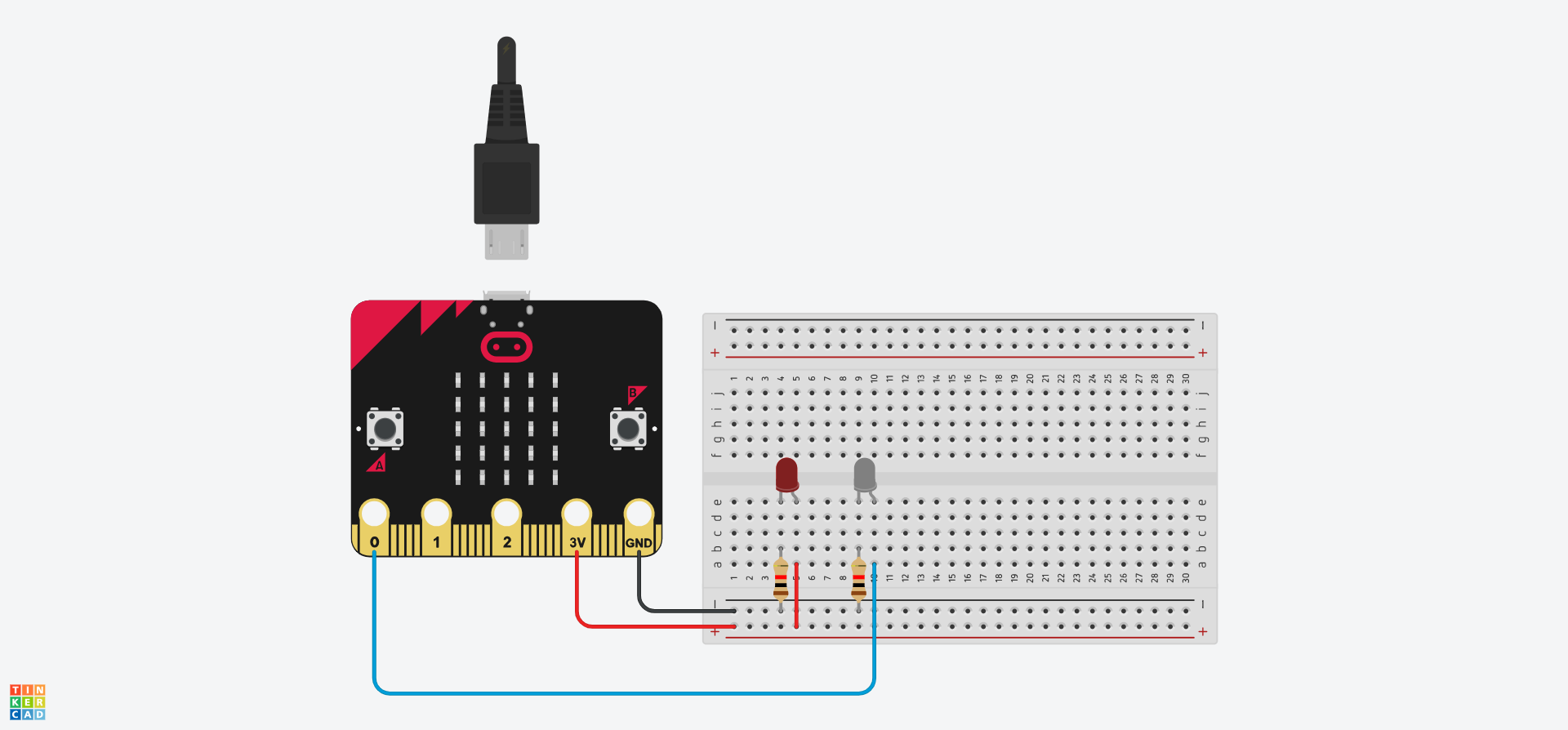
We need a red LED to show when the system is turned on. The required circuit is shown in the diagram below, recreate this on a breadboard in Tinkercad.
When using a breadboard, the first thing you should do is connect the negative rail to a GND pin with the positive rail connected to a power pin.
Remember, the LED's cathode connects to the GND pin.
This LED is connected to the power on the Micro:Bit. This means it will always be on when the Micro:Bit is running, no programming is required.
If you are still stuck, please use the answer button below.
To help plants grow in our 'smart greenhouse', we need to provide them with light all the time. Add a white LED to your breadboard as shown here:
Tip: The components do not need to be in the same left to right order on the breadboard as they are in the diagram - as long as the wiring for each matches.
LEDs are always connected to the GND pin. However, the anode is either connected to a programmable pin or the power pin.
You can change the colour of an LED in Tinkercad by clicking on it and then changing the colour in the information box that appears in the top right of the work area.
There is a bug in Tinkercad that makes LEDs partially light up when you start the simulation, even if not programmed to. You can fix this by setting your pins to LOW inside the program's 'on start' block.
If you are still stuck, please use the answer button below.
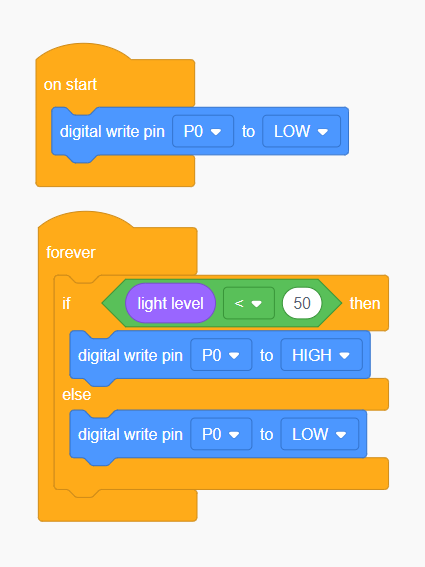
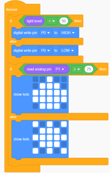
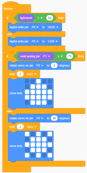
We have connected the white LED to a programmable pin. We do not want to waste electricity by having the light on all the time - instead, we only need it when it's dark. So, program your Micro:Bit to turn on when the light level is less than 50.
Tip: Remember, the Micro:Bit has it's own built-in light sensor.
You will need an if-statement to check if the light level is less than 50.
To turn the light off again when it is no longer needed, you will need an else-statement.
The white LED is a digital output of on (HIGH) or off (LOW).
Your new statements need to be in the forever loop so the program keeps checking the light level and adjusting the LED to on or off.
To test in the Tinkercad simulator, you can alter the light level on the Micro:Bit's control panel (the slider control marked with a sun symbol).
If you are still stuck, please use the answer button below.
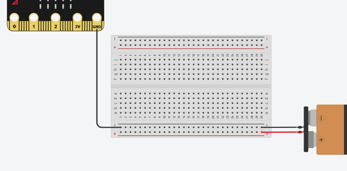
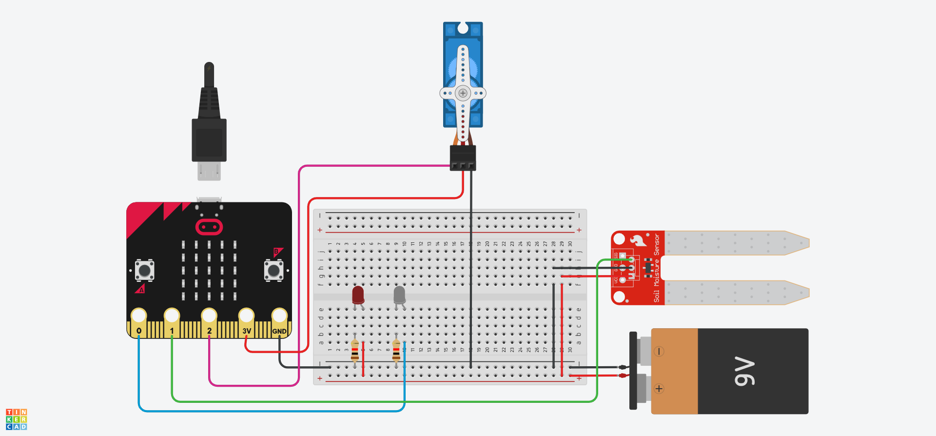
Additional Power: The Micro:Bit can only provide 3V of power. To continue building our 'smart greenhouse' we shall need more than this. So, we need to add a power supply to our circuit. Below is a demonstartion of how to do this.
When using an additional power supply, disconnect the Micro:Bit's 3V pin from the breadboard.
Our circuit will need more than 3V of power. Use the below circuit diagram to add a new power supply to our circuit.
Make sure you have removed the wire that connects the Micro:Bit's 3V pin to the positive rail of the breadboard. Otherwise, you will destroy the Micro:Bit as too much power will be trying to run through it.
Pay attention to the voltage asked for in the circuit diagram and select the appropriate battery/batteries.
If you are still stuck, please use the answer button below.
Connecting components off the breadboard: Almost all components can be inserted into a breadboard. However, we sometimes need a component to be seperate. This might be because the main breadboard is inside a protective box and/or that a component needs to be moved around. To connect a component off the beadboard, see the below examples.
LED on the breadboard:
LED off the breadboard:
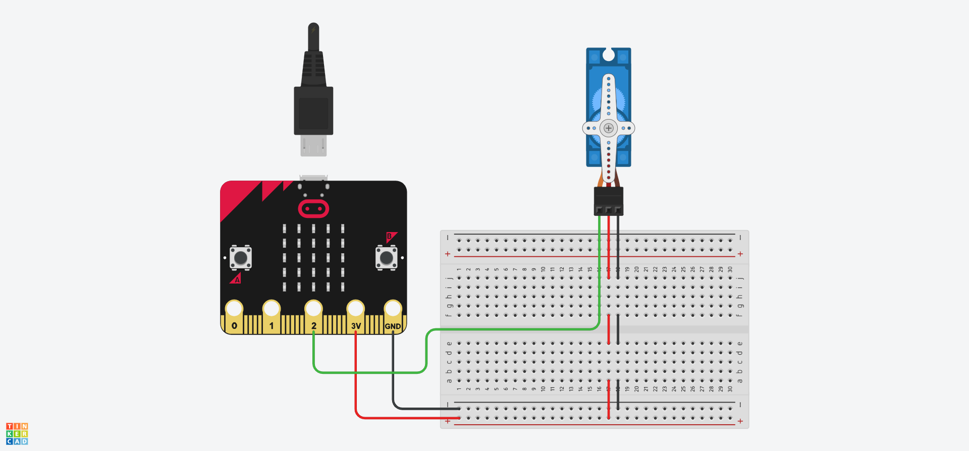
Servo on the breadboard:
Servo off the breadboard:
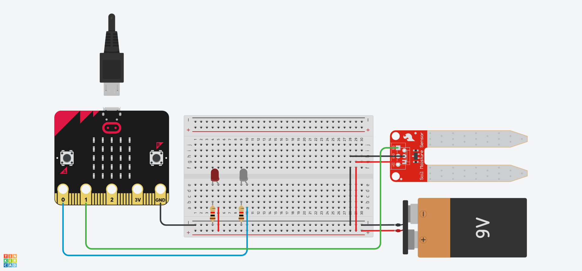
Our 'smart greenhouse' needs to know how damp the soil is. This means we need a soil moisture sensor that can be inserted into a pot. Add the new component off the breadboard using the circuit diagram below.
The pins on the soil sensor are not in the same order in Tinkercad as displayed in the diagram. You can hover the mouse over a connection in Tinkercad to identify it.
The wire connected to the control pin of the sensor connects directly to the Micro:Bit, not via the breadboard.
If you are still stuck, please use the answer button below.
In your program add the necessary blocks to make the Micro:Bit screen show an image for when the soil is wet (greater than or equal to 75) and another image to let the user know it's too dry.
Use images that are easy to understand the meaning of. For example, a water droplet to say the soil is wet, while a sun shows when it is dry.
We want to use a basic image here to keep the program running efficiently. If we were to include animations or text messages, it would slow the program down and therefore our 'greenhouse' will not adapt fast enough to changing conditions.
You will need to use a new if-statement using the soil moisture sensor measurments, with an else-statment to do the opposite.
The program needs to read the analog input of the soil moisture sensor.
You can test the program in the simulation by selecxting the soil moisture sensor and adjusting the sliging bar to increase or decrease the value.
If you are still stuck, please use the answer button below.
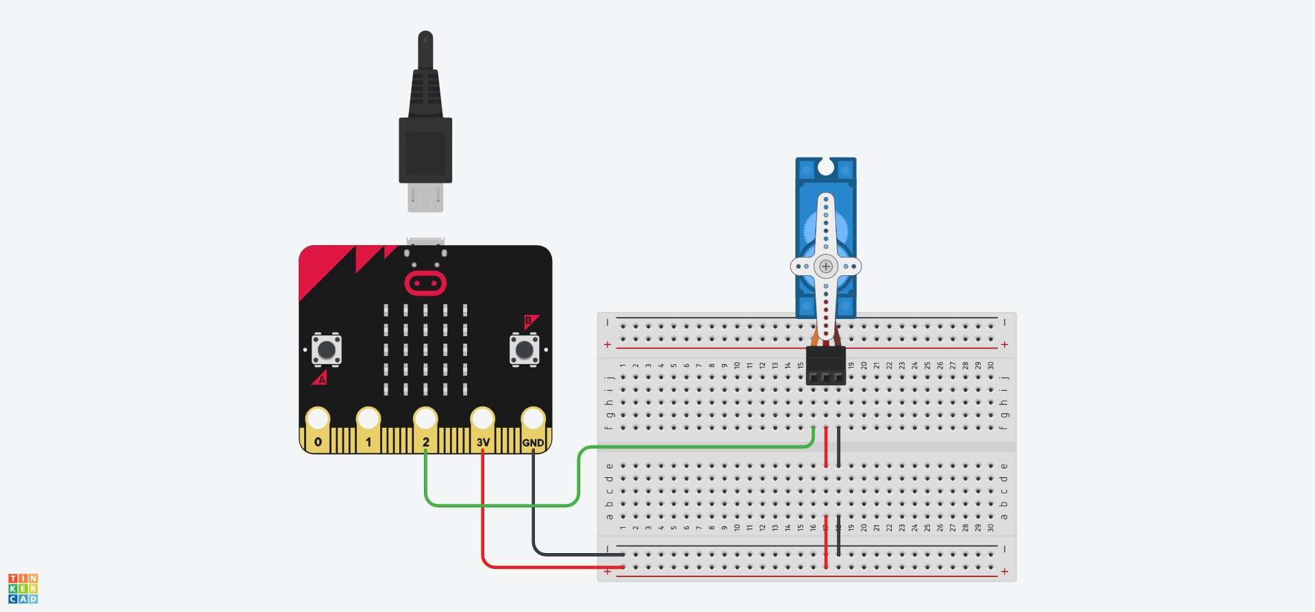
Connect a servo off the breadboard and to pin 2 on the Micro:Bit.
Tip: In Tinkercad, you want to select the blue Micro Servo for this.
You can use the example images in the Silver Level section to help with the wiring.
Unfortunately, the servo cannot handle 9V. So, you will need to connect it to the 3V pin on the Micro:Bit directly. This means only the GND terminal of the servo will connect to the breadboard.
If you are still stuck, please use the answer button below.
Imagine that this servo is turning a tap on and off to provide water to our plants. We only want the tap to release water when the soil is dry. Turning the servo to 90° turns the tap on, 0° turns it off again. Write a program for this.
We already have an if/else-statement to see if the soil need watering or not. This is where we can add the servo commands.
The servo is an analog output.
Include a wait block for servo movements to provide with the time needed to complete the action before the program resumes.
If you are still stuck, please use the answer button below.
Congratulations! You have successfully built and programmed the circuit for a Micro:Bit controlled greenhouse.
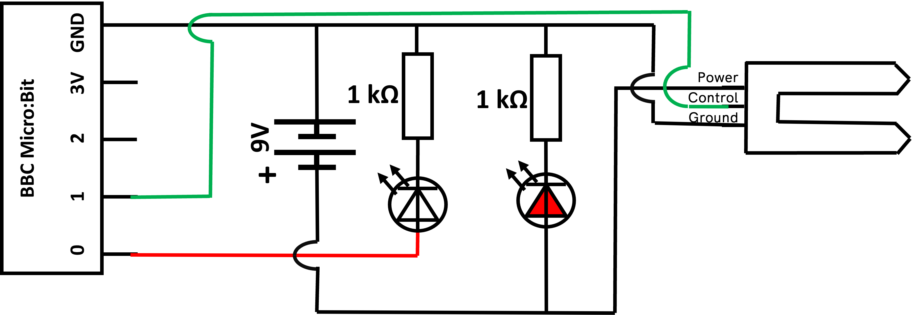
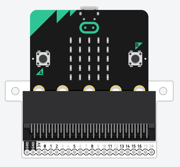
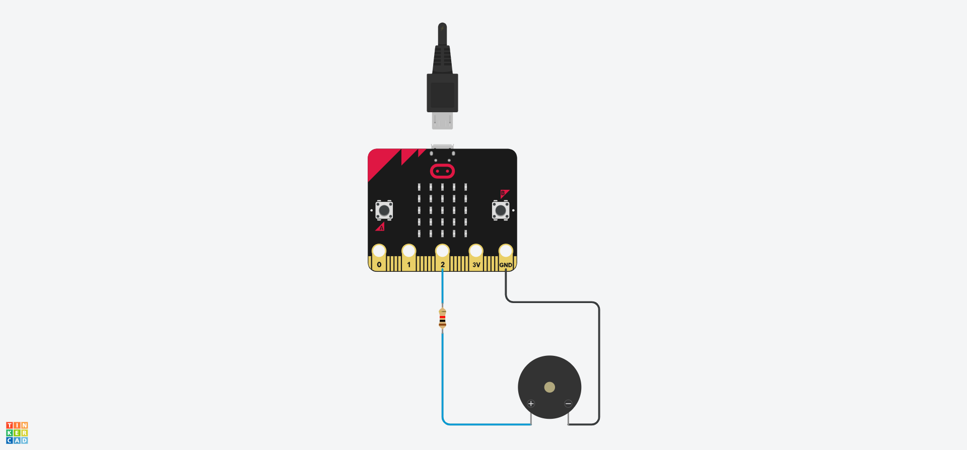
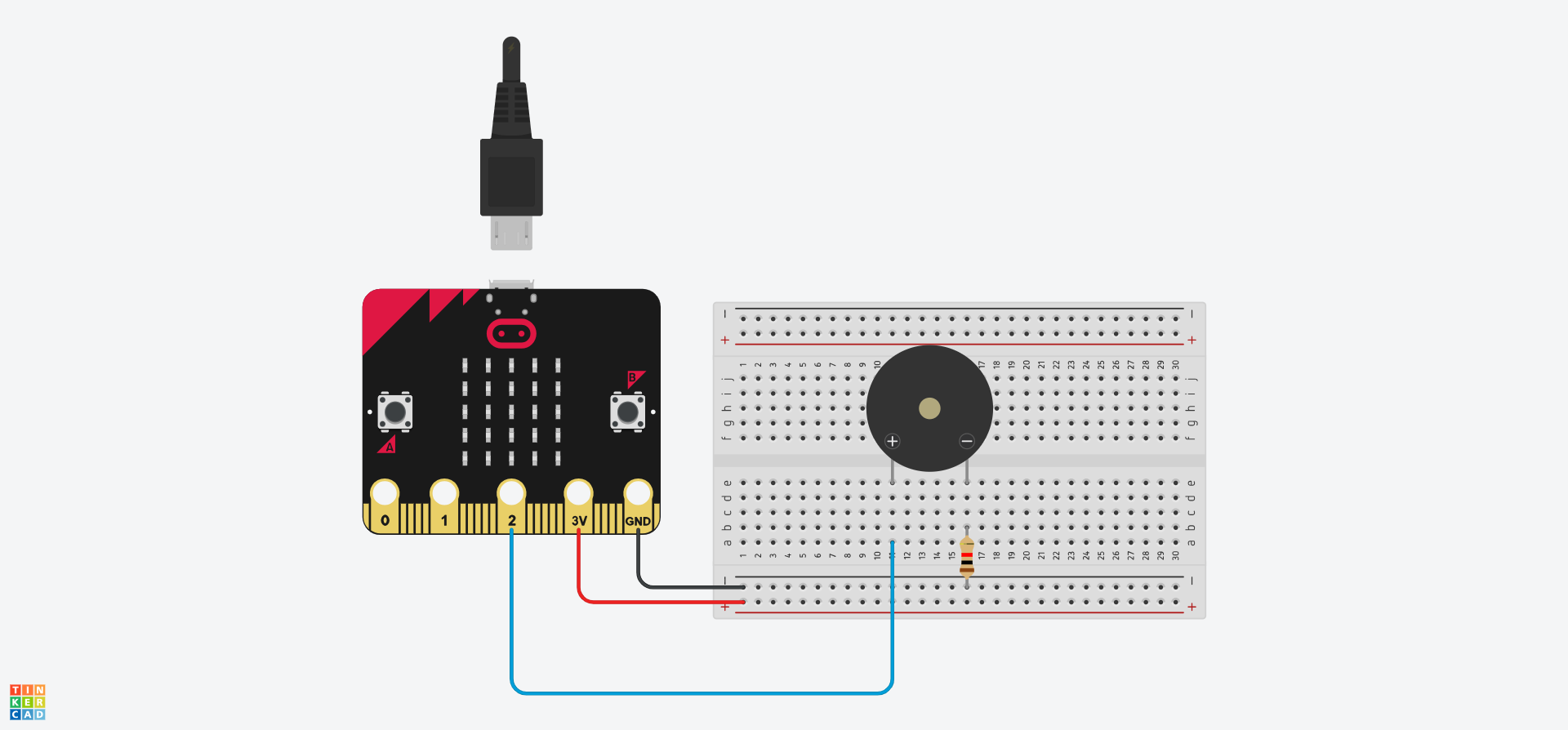
New Component - Breakout Board: The Micro:Bit has 3 main programmable pins. However, as covered in our Micro:Bit Series, there are more available by accessing the smaller sections of the pin strip. For attaching wires to these additional pins in Tinkercad we use a breakout board.
Now, we have 10 programmale pins (0, 1, 2, 5, 8, 11, 13, 14, 15, 16) we can connect components to. There are other pins shown in grey - these are already in use by the built-in LEDs, buttons, and sensors on the Micro:Bit.
The +/- symbols on the Piezo Buzzer in Tinkercad inform you as to where they are connected (so the negative one connects to the GND pin and the positive to the power or one of the programmable pins).
Wiring without a breadboard:
Wiring using a breadboard:
This is a component that poduces a buzzing sound when active. This can be programmed as either a digital or analog output. Digital allows you to turn the default buzz on and off. Analog allows us to program the tone and duration of the buzz.
Create a new circuit in Tinkercad made up of a Micro:Bit with a breakout board, a breadboard, 3 programmable LEDs (red, yellow, and green) with a resistor each, an additional 9V power supply, and a Piezo Buzzer with a resistor.
Can you create a program for this circuit that acts as a traffic light with the buzzer acting as an alarm to let pedestrians know it is safe to cross the road.
Draw a circuit diagram of you traffic light system for others to use.
Video Lesson:
Exercises:
This session looks at creating circuits in Tinkercad with an Arduino Uno.
All learners should start with the bronze level and work their way up as far as they can.
Click on each challenge heading to expand.
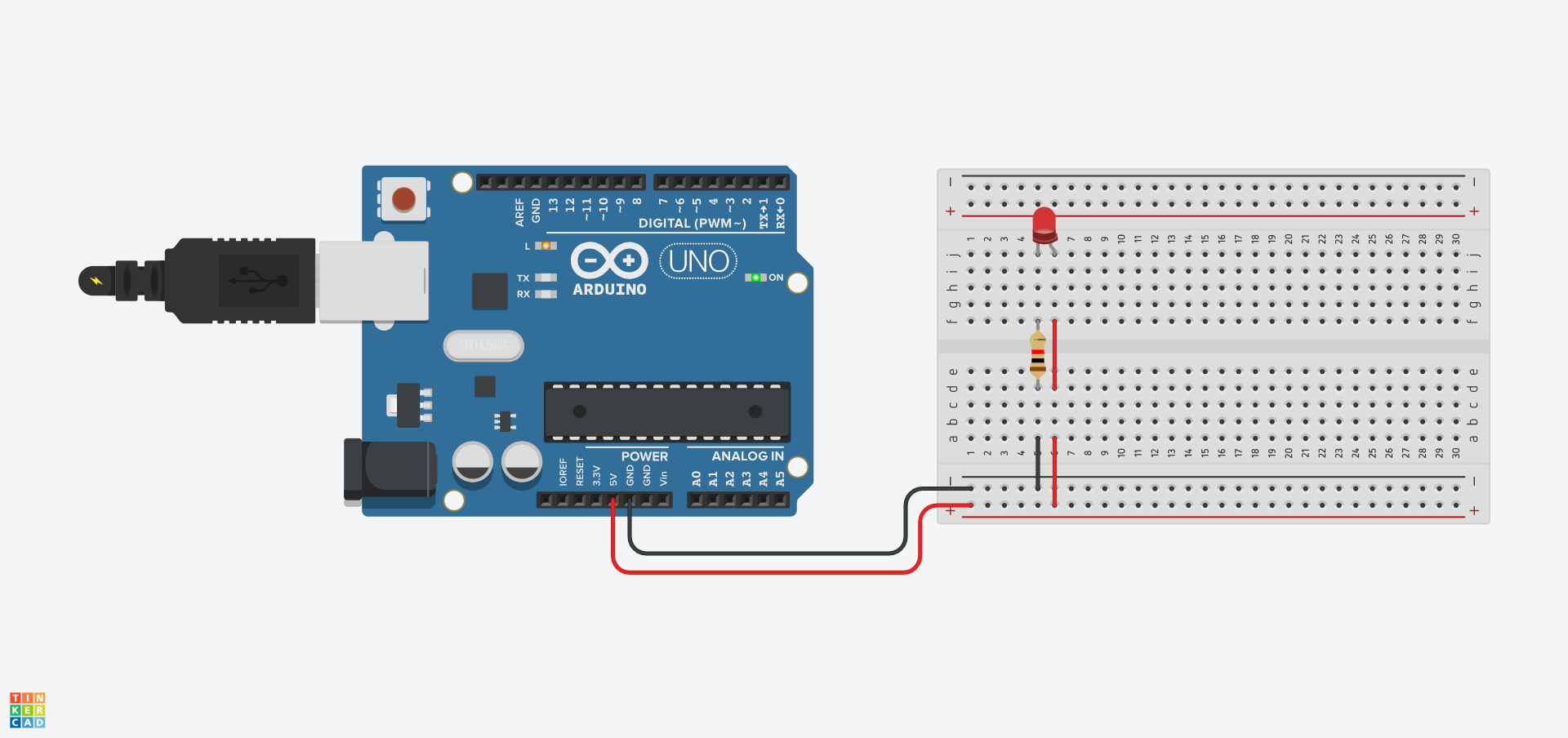
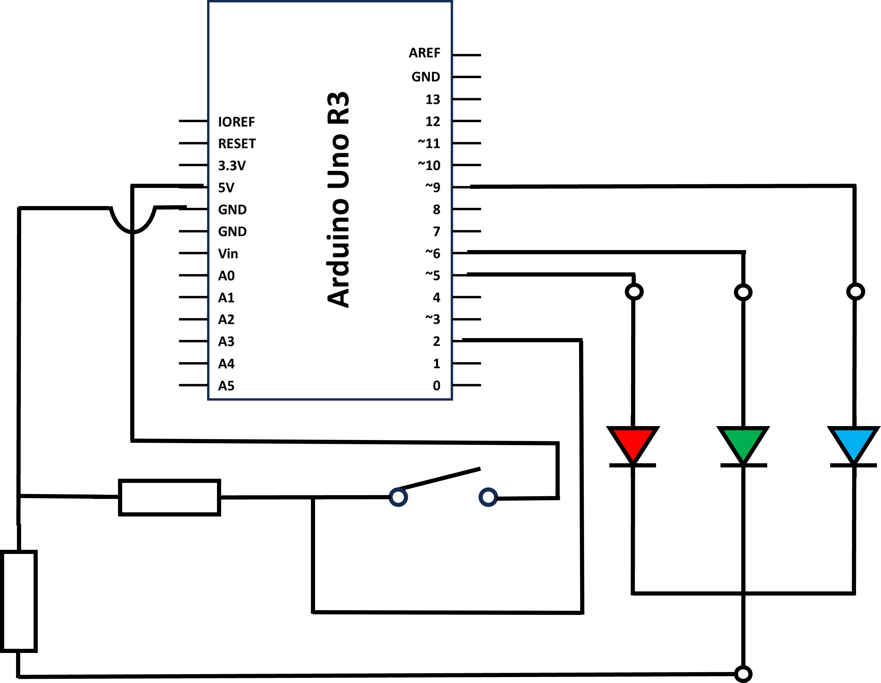
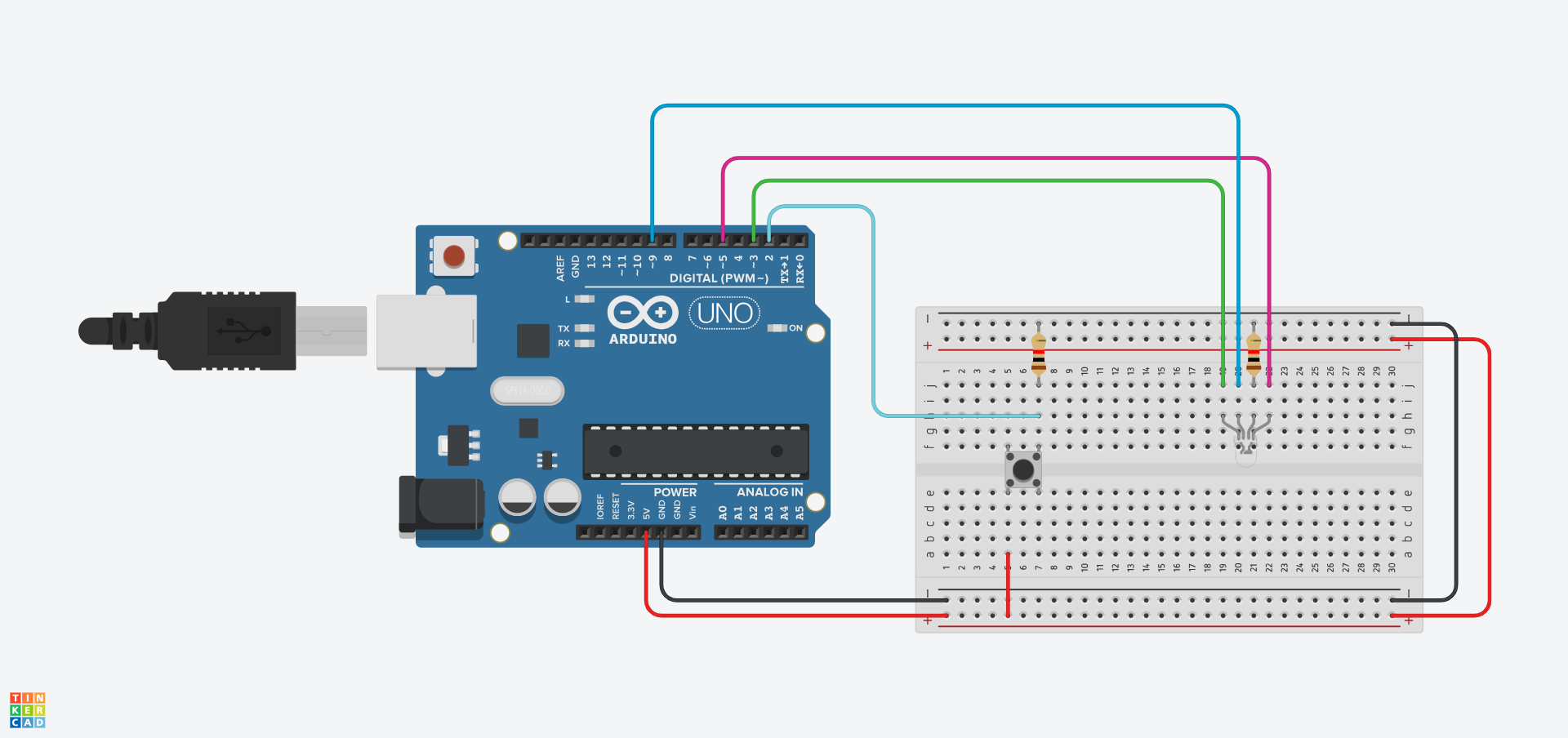
Create a circuit with an Arduino Uno R3, a breadboard, a resistor, and an LED. Have it wired so the LED is always on (does not require programming).
Tip: Use the 5 Volt connection on the Arduino for this circuit.
Connect the negative row on the breadboard to one of the GND pins on the Arduino.
The positive row on the breadboard should be connected to the 5V pin on the Arduino.
We have created a circuit diagram to help:
If the LED does not light-up, check that you have the cathode connected to the negative and the anode to the positive.
If you are still stuck, please use the answer button below.
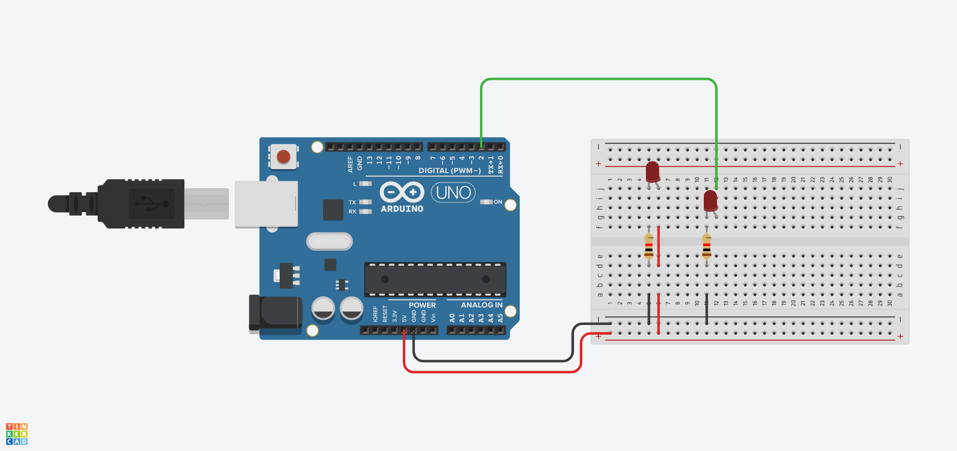
Connect another LED with a resistor to pin 2.
Tip: This will not light up in the simulator as it does not have a program yet.
This LED will be connected to the GND (negative terminal) and Pin 2.
We have created a circuit diagram to help:
If you are still stuck, please click on the answer button below.
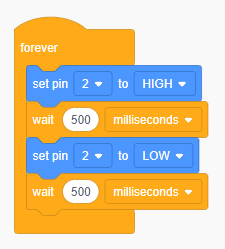
Program the Arduino (using blocks) to have the LED on pin 2 flash on and off using a wait time of 500ms between changes.
Tip: Remember to include the wait after both turning the light on and off.
An LED is an output, and the wait is a control block.
The wait block can be changed to milliseconds.
If you are still stuck, please use the answer button below.
Before you start this challenge, please delete any code from your forever loop ready to create a new program.
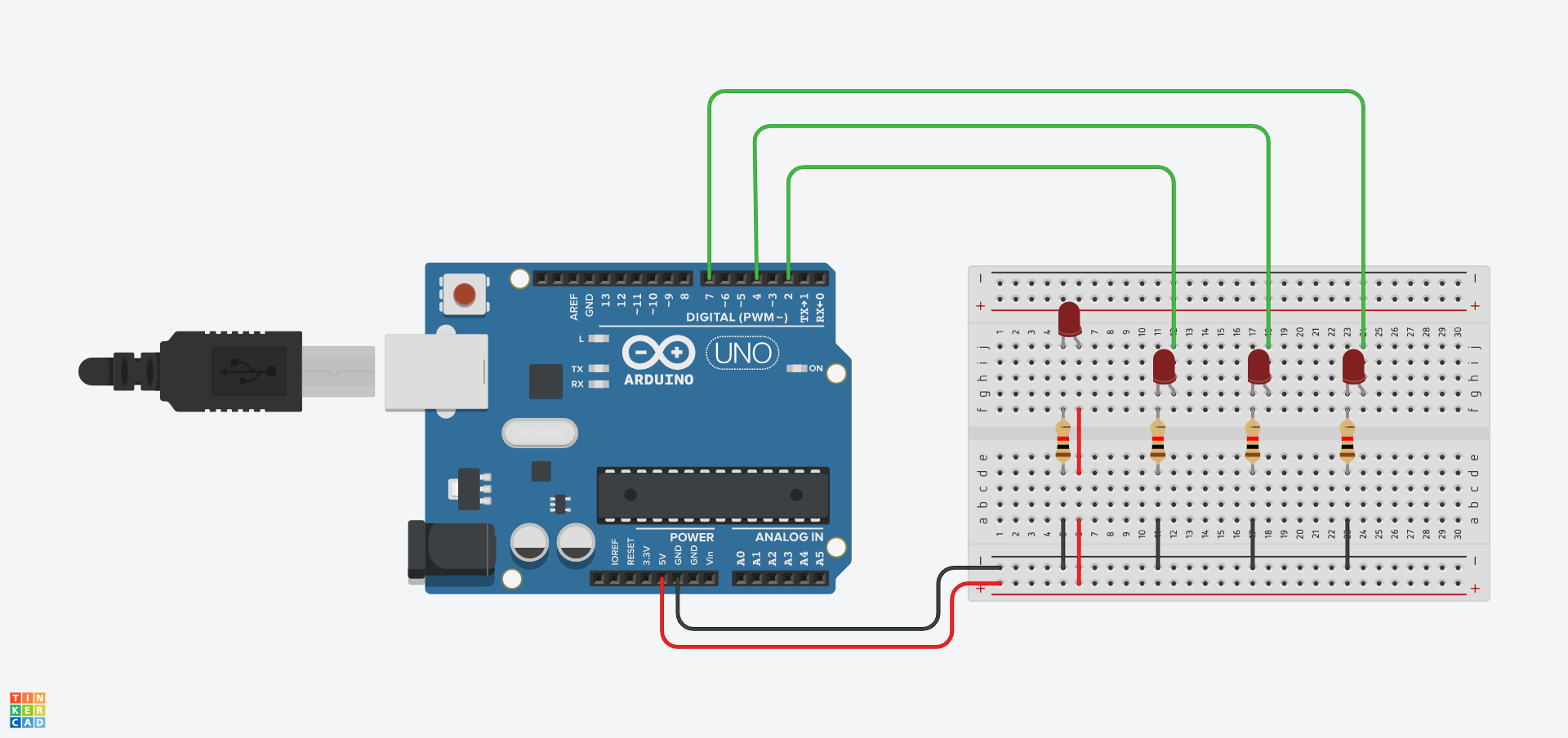
Add two more LEDS (with resistors) to your circuit. One should connect to pin 4, the other to pin 7 on the Arduino.
We have produced a circuit diagram which may help:
If you are still stuck, please use the answer button below.
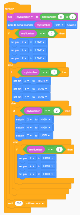
In your program, create a variable called myNumber and in the forever loop have this variable set to a random number between 0 and 3. Have this value show on the serial monitor.
Tip: The serial monitor can be opened by clicking on the serial monitor bar at the bottom of the code section.
If the numbers are being produced too quickly, add a wait block to the forever loop.
We use the serial monitor to see readings, information, and to debug our programs.
Now create a program that will light up the same number of lights as the value of myNumber.
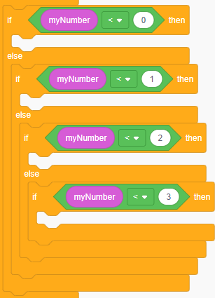
Tip: Tinkercad blocks do not include 'else if' statements. Instead, you can use if-statements stacked inside else-statements.
Here is an example of how you can stack the else and if-statements to recreate the same effect as using an 'else if' statement.
Don't forget to turn off the LEDS when they are not needed.
You will need to put a wait at the end of the forever loop to ensure the lights have time to turn the LEDs on or off.
If you are still stuck, please use the answer button below.
Create a new circuit for this challenge.
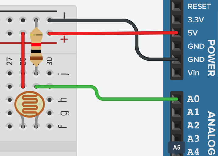
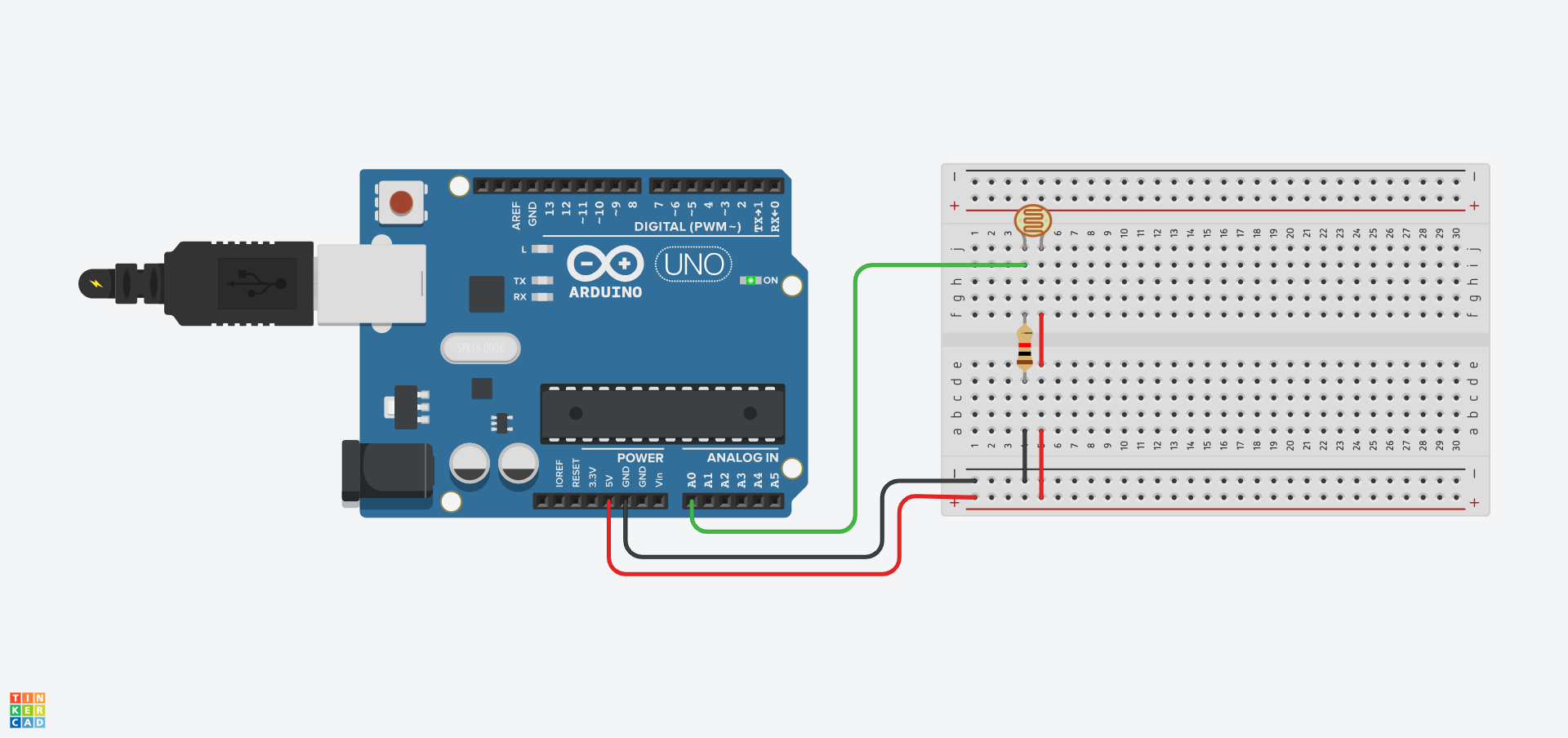
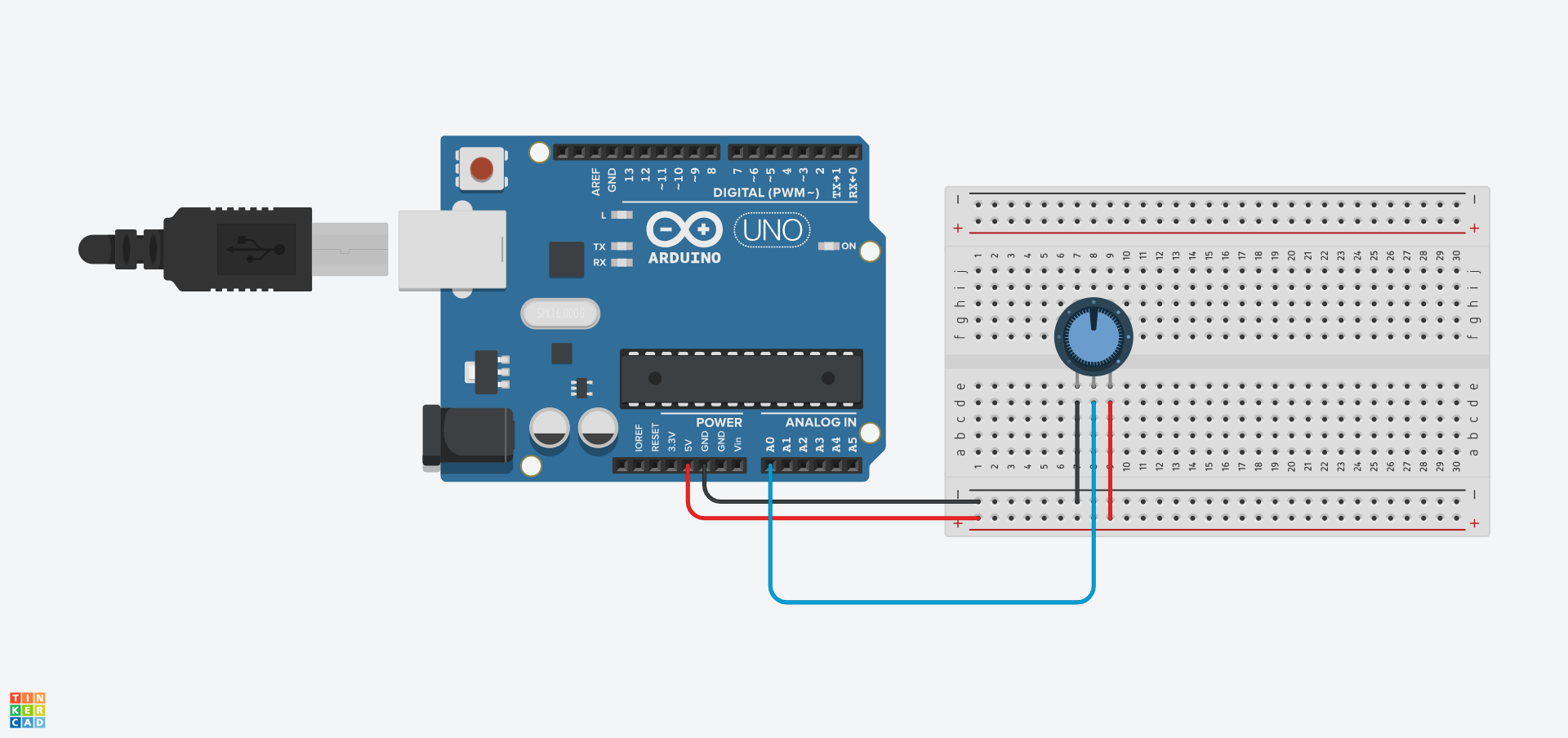
Create this circuit on a breadboard in Tinkercad:
In this case the LDR is connected to power all the time whilst the A0 pin allows us to collect data from the component.
Here is an example of how you could connect together the LDR with the Arduino:
If you are still stuck, please use the answer button below.
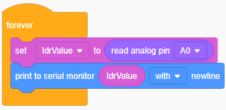
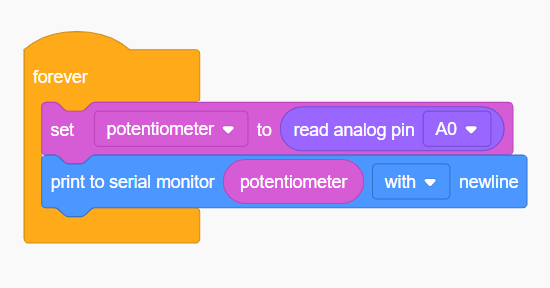
In the program, create a variable and set it to the analog reading from the LDR/Photoresistor. Have these values printed in the serial monitor. Use this to determine the full range of values the LDR can generate.
Tip: You can change the light level by clicking on the LDR/Photoresistor during the simulation and use the slider bar that appears.
Choose a suitable variable name, such as ldrValue.
Remember, you can open the serial monitor by clicking on the bar at the bottom of the coding window.
If you are still stuck, please use the answer button below.
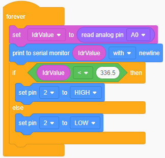
The range of values for the LDR/Photoresistor is 6 to 679.
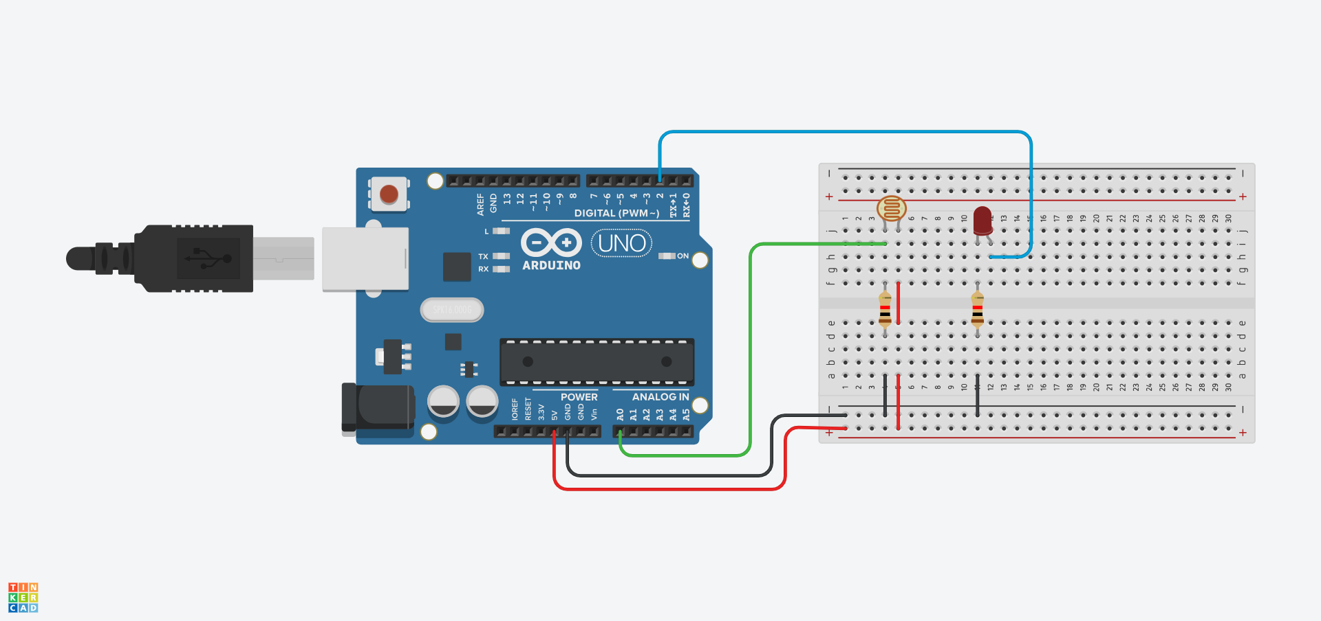
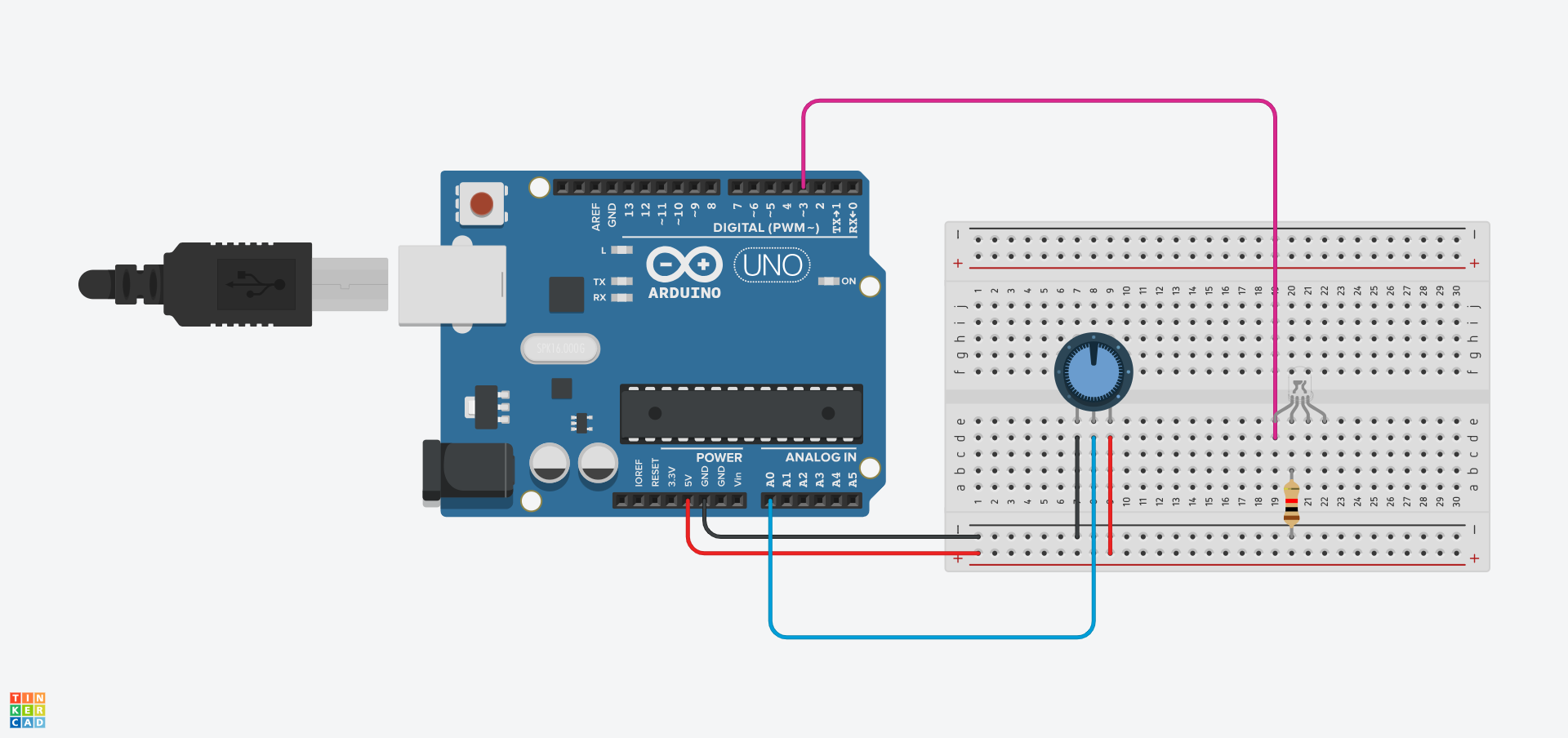
Add an LED to the circuit and connect it to pin 2. Program the LED to turn on when the LDR reading is less than the middle of its range.
Tip: Remember to turn the LED off when the LDR value increases above the middle range value.
Use an if and else statement for the LED to make sure it turns off when the condition is no longer true.
The middle value can be calculated using (679 - 6) ÷ 2.
If you are still stuck, please use the answer button below.
Create a new circuit, using a breadboard, that takes readings from a temperature sensor.
Add a blue, a red, and a white programmable LED to the circuit.
Write a program for your circuit that has the blue light turn on when the temperature is below 0°C, the white light when the temperature is between 0 and 35°C, and the red light when the temperature is 35°C or more.
Video Lesson:
Exercises
This session looks at creating circuits in Tinkercad with an Arduino Uno.
All learners should start with the bronze level and work their way up as far as they can.
Click on each challenge heading to expand.
Connect a potentiometer to an Arduino (using a breadboard), then write a program to print the values of the potentiometer into the serial monitor and work out its range.
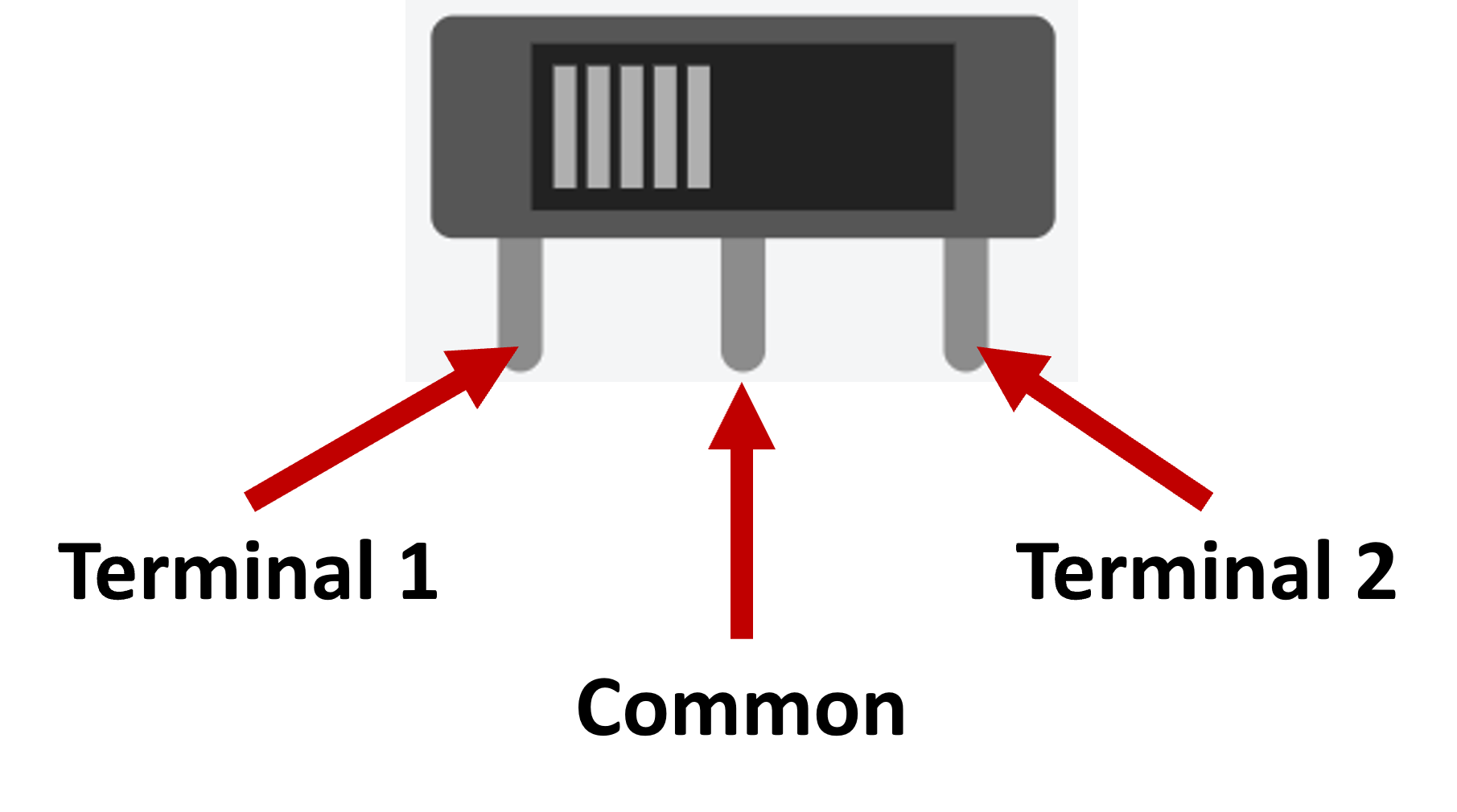
Tip: The potentiometer has three pins. Terminal 1 goes to the GND, the Wiper goes to an analog input pin, and terminal 2 goes to the 5V pin on the Arduino.
Whenever a circuit requires a breadboard, the first thing you should do is connect the breadboard to the power terminals (in this case, the 5V and GND pins on the Arduino).
You will need to create a variable to store the potentiometer value in. Then you can have the program print this variable value to the serial monitor.
If unsure how to use the serial monitor, check the silver level exercises in Session Four.
If the dial on the potentiometer is pointing to zero (all the way round to the left), but the value in the serial monitor is 1023, the terminals have been wired the wrong way round.
To test the program, you can select a potentiometer, after starting the simulation, and then click and drag the dial up and/or down. The value in the serial monitor should change as you do this.
If you are still stuck, please use the answer button below.
The Circuit:
The Program:
You may have used a different analog input pin on the Arduino - just make sure the pins used in the code match with your wiring.
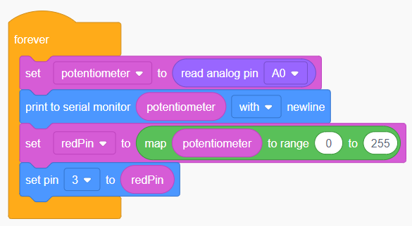
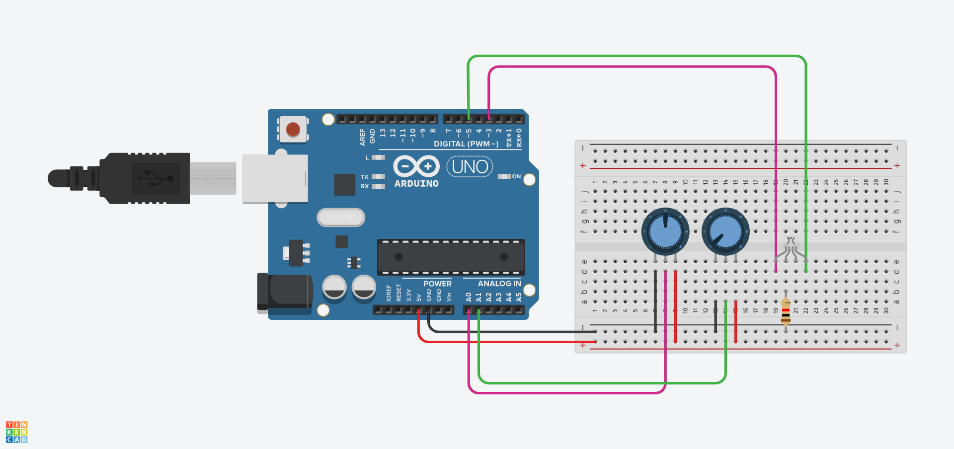
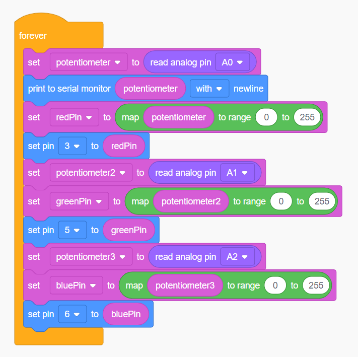
Add a RGB LED to the circuit. Connect the red pin to an analog output pin (those marked with a '~' before the number). In the program, map the potentiometer input to the red pin of the RGB LED. The higher the input, the brighter the red light.
Tip: You will need to add a resistor between the cathode of the RGB LED and the GND connection to prevent it from exploding.
The RGB LED's cathode needs to be connected to the GND pin.
The red pin of the RGB LED needs to be connected to an analog output pin (3, 5, 6, 9, 10, or 11) on the Arduino.
You will need to create a variable for the red pin to store the mapping value.
You are mapping the potentiometer variable (created in the previous step) to the LED's range of 0 to 255.
When testing, the RGB LED should be off when the potentiometer value is 0, and then increase in brightness as the dial is turned up.
If the LED shows an explosion when the dial is turned up, then you are either missing the resistor or it's incorrectly placed.
If you are still stuck, please use the answer button below.
The Circuit:
The Program:
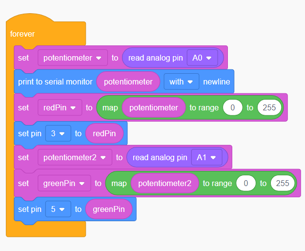
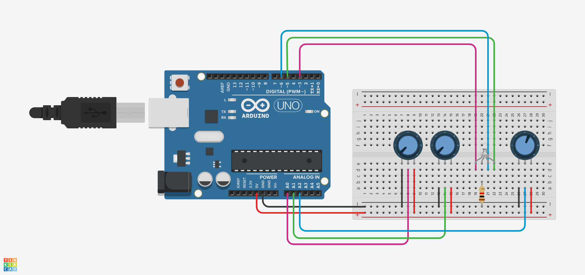
Add a second potentiometer and map its values to the green pin of the RGB LED.
Tip: You may want to move the components around to make space on the breadboard. Alternatively, you can use the larger breadboard from the component list.
You will need to create a new variable for the second potentiometer and for the green pin value on the RGB LED.
You can use the serial monitor to test the wiring.
Remember, to map an analog value to an LED it needs to be connected to one of the numbered pins marked with a '~'.
If you are still stuck, please use the answer button below.
The Circuit:
The Program:
Finally, add a third potentiometer mapped to the blue pin of the RGB LED.
Repeat the same process as we did for the second potentiometer.
Remember to use different variable names again.
If you are still stuck, please use the answer button below.
The Circuit:
The Program:
You now have a circuit that allows you to create any colour of light by adjusting the potentiometer dials.
Create a new circuit for this challenge.
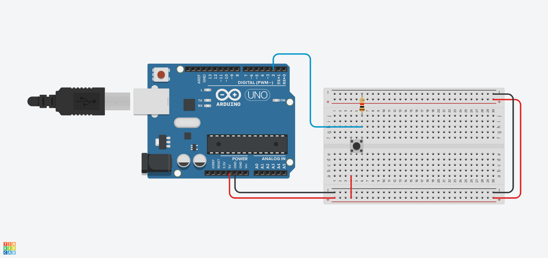
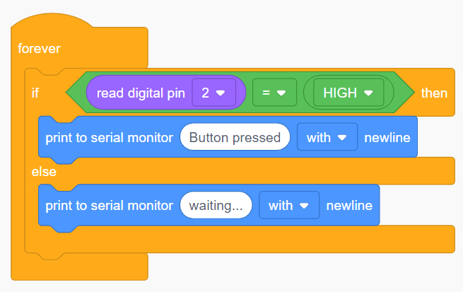
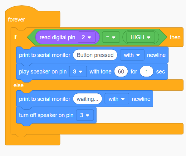
Connect a push button to an Arduino using a breadboard. Have the serial monitor show if the button is pressed or not.
Tip: A button is either on (HIGH) or off (LOW) meaning this is a digital input.
You can connect the bottom negative and positive rows of the breadboard to the matching top rows - this provides us with more connection points to the power and ground.
You will need to include a resistor for this component.
For the program, you will need to use an if/else-statement to send messages to the serial monitor.
If you are still stuck, please use the answer button below.
The Circuit:
The Program:
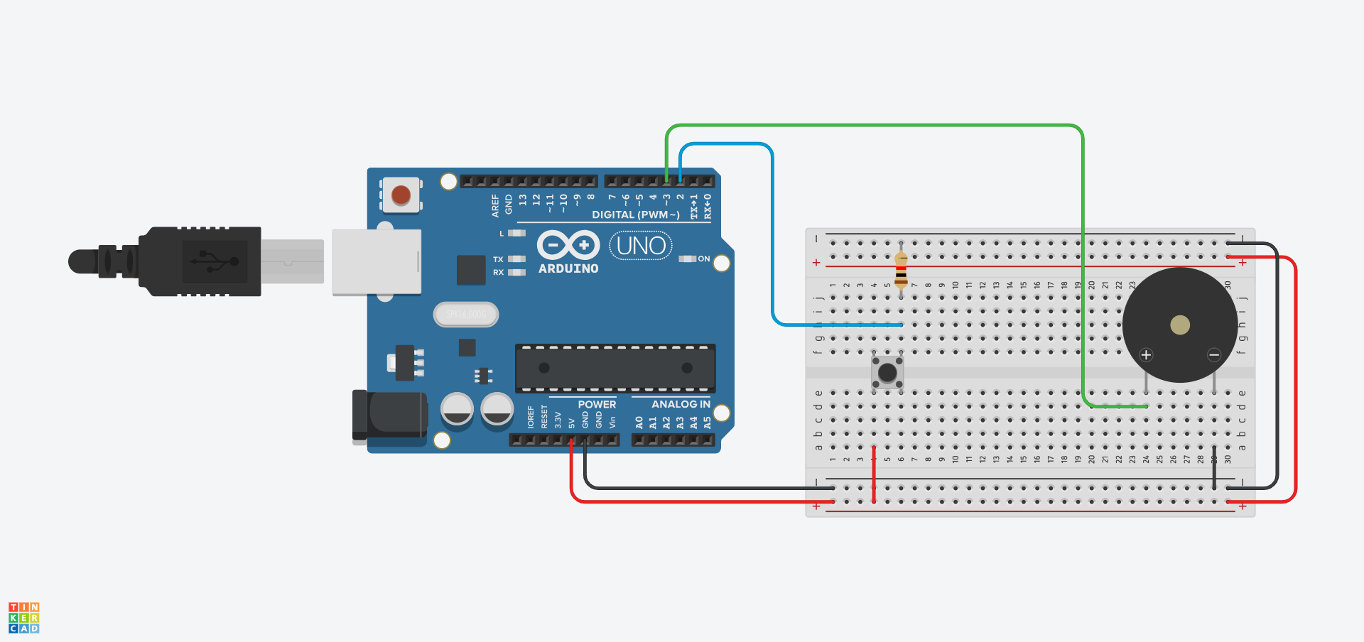
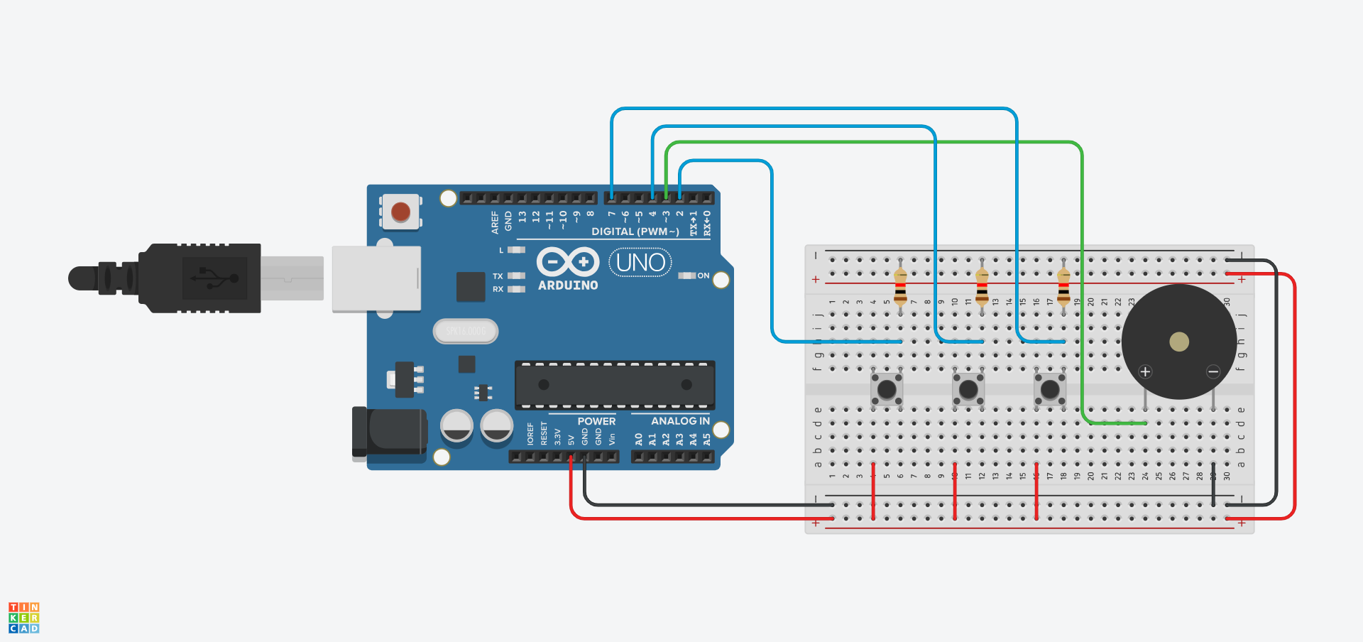
Add a piezo buzzer to the circuit and program it to sound when the button is pressed.
Tip: The buzzer terminals are labelled as to which terminal they connect to. So, the negative connects to the GND, whilst the positive needs to connect to a programmable pin.
The Piezo buzzer is an analog output as we can set the tone it uses. This means it needs to be connected to one of the analog output pins.
Use the speaker output blocks for the buzzer - these allow us to set the tone played.
Don't forget to stop the buzzer if the button is not pressed.
If you are still stuck, please use the answer button below.
The Circuit:
The Program:
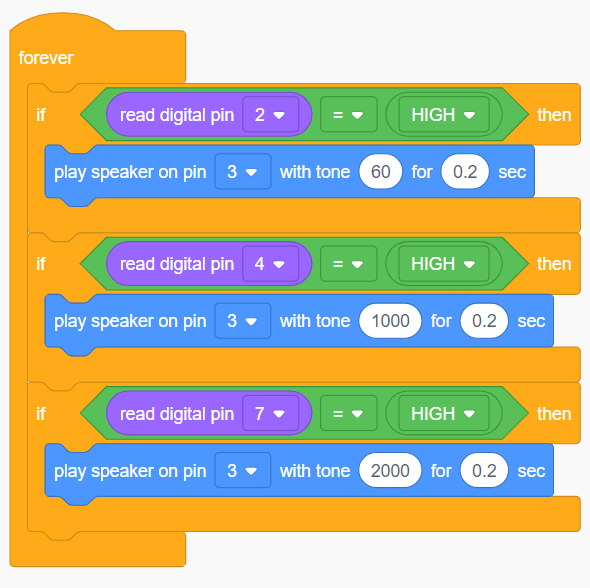
Now add two more buttons and program them to play different tones using the buzzer.
The range of tone values for the Piezo is 27 - 3950. The larger the value, the higher the tone.
If you set short times (such as 0.2 seconds) for the tones, you don't need an else-statement to turn the Piezo off. You can also remove the use of the serial monitor as it's no longer necessary.
If you are still stuck, please use the answer button below.
The Circuit:
The Program:
You are now able to create an electronic musical instrument.
Create a new circuit for this challenge.
Create this circuit with a breadboard, using a push button as the switch:
The button in this diagram is wired the same way as the one in the silver level challenges.
If you are still stuck, please use the answer button below.
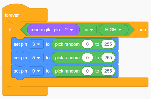
Write a program where pressing the button generates a different random number between 0 and 255 for each RGB LED colour pin.
There is a random number block in the maths menu.
If you are having problems and need to debug the program, introduce variables for each colour pin value and whether the button is pressed and use the serial monitor.
If you are still stuck, please use the answer button below.
Here are some ideas, using what we've learnt in this session, to create new circuits:
Your own doorbell that plays a tune when the button is pressed.
A buzzer controlled by a potentiometer so the pitch changes as you adjust the dial.
An alarm system that makes a buzzer sound if buttons are not pressed in the correct order.
Video Lesson:
Exercises:
These challenges involve creating circuits to revise all the components we've covered in this topic's videos.
All learners should start with the bronze level and work their way up as far as they can.
Click on each challenge heading to expand.
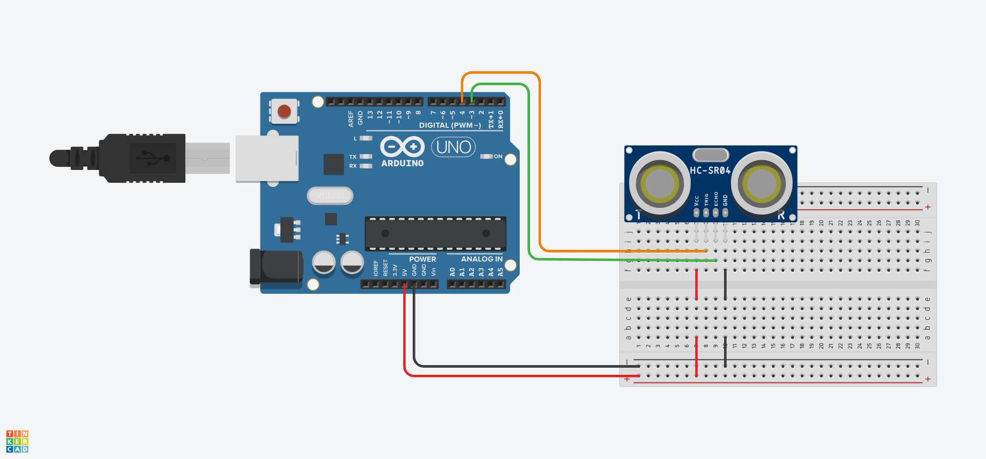
Use this circuit diagram to connect an ultrasonic sensor to an Arduino in Tinkercad. Don't forget to include a breadboard.
Tip: The trigger pin on the ultrasonic sensor is digital, whilst the echo pin is analog.
The circuit diagram matches the wiring shown in this session's video.
For this exercise, you can insert the ultrasonic sensor into the breadboard.
If you are still stuck, please use the answer button below.
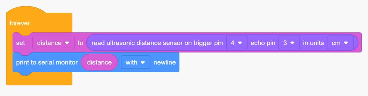
Have the ultrasonic sensor readings print to the serial monitor.
Tip: You can adjust the reading by selecting the sensor whilst the simulation is active and then moving the circle around within the highlighted area.
It is good practice to create and use variables for sensor values.
If the serial monitor only prints the number 0, you need to first check your wiring, and then check the pins' numbering matches in the code.
If you are still stuck, please use the answer button below.
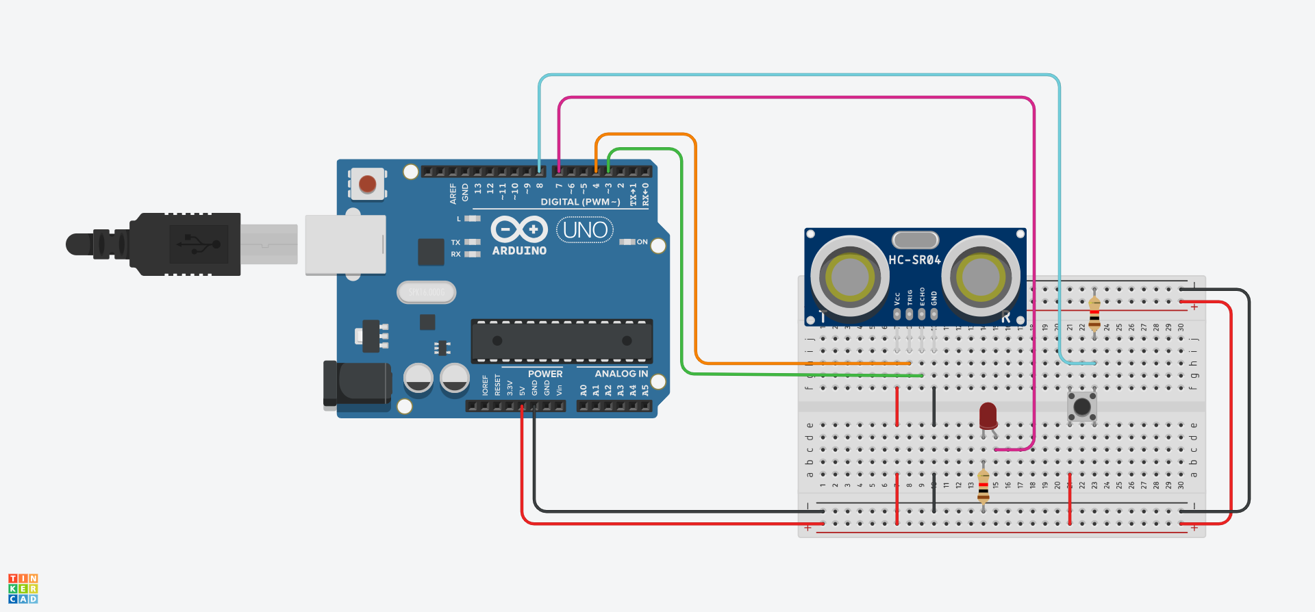
Add a push button and an LED to the breadboard and connect them to the Arduino.
Tip: The LED is being used as a digital output for this exercise.
You will also need to add a resistor to each of these components.
Here is an example of how to wire up the push button:
As your ultrasonic sensor is already using pin 4 on the Arduino, you will need to choose a different digital pin for your push-button.
When wiring a push button, make sure you connect the top rails of the breadboard to the bottom.
The LED needs to be connected to a programmable pin and the GND pin.
If you are still stuck, please use the answer button below.
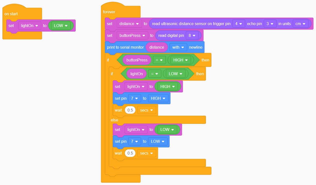
Create a variable to store whether the LED should be on or off. Write a program where pressing the button will check if the light is on or off and then change it. This means that when you press the button it will turn the light on, another press will then turn it off, then on, then off, and so on.
Tip: You will need to change your new variable each time the button is pressed. As this is a digital input, the values used are HIGH (on) and LOW (off).
Following good practice, create a variable to store the value of the button input.
Use an if-statement to check if the button is pressed.
Inside this if-statement you will need an if/else-statement checking the status of the LED (if it's on or not).
If the light is off, turn it on and change the variable for the light to on. Else, turn it off and change the light variable to match this.
Include brief pauses (0.5 seconds) for either condition to prevent a button press registering more than once.
If you are still stuck, please use the answer button below.
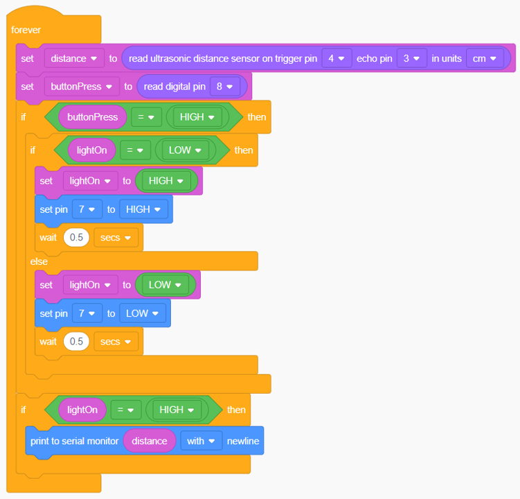
Now, have the serial monitor only print the ultrasonic sensor readings whilst the LED is turned on.
Tip: This is creating a program where the LED acts as a power indicator for the ultrasonic sensor.
This means moving the print to serial monitor command to a new if-statement checking if the switch is on.
If you are still stuck, please use the answer button below.
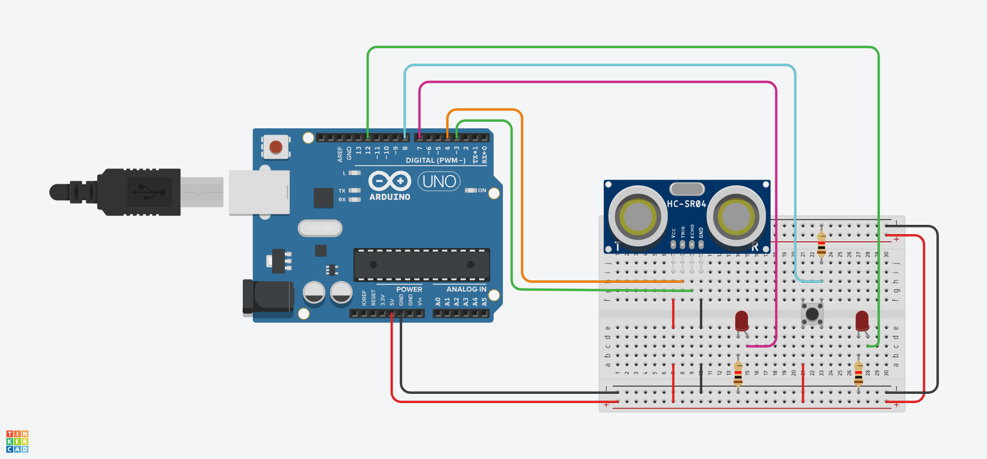
Connect a second LED to your breadboard and Arduino. Program this new LED to only light up when the ultrasonic is 'active' (the first LED is on) and detects an object less than 100cm away.
Tip: Stacking if-statements inside each other, acts the same as a Boolean 'and' operator.
The new LED needs to be connected to a digital output pin.
Do not put your new if-statement inside the one for checking if the button is pressed or it will only take a measurement at that moment.
You will also need an else-statement to turn this new LED off again when the object moves away.
If you are still stuck, use the answer button below.
The Circuit:
The Code:
Create a new Tinkercad circuit using a breadboard that includes an Arduino, six LEDs with resistors, and an ultrasonic sensor.
Tip: All the LEDS are digital outputs for this challenge.
With so many components in this circuit, consider colour coding your wires. Black for GND, Red for 5V, and then different colours for the programmable.
If you want to spread components out, you could connect multiple breadboards, or use a larger one.
Remember that the ultrasonic sensor's echo pin is analog so needs to be connected to a programmable pin with a '~' symbol next to the number.
If you are still stuck, please use the answer button below.
Now, program this circuit so the closer an object is to the ultrasonic sensor, the more lights that show. Use 50cm ranges to determine the number of lights. So, if the object is 0-50cm away all the LEDs are on, 50-100cm has 5 LEDs on, etc. If an object is outside the maximum range or the detection area, the LEDs should all be off.
Tip: Stack an if-statement into an else-statement to create an else-if statement.
As we are using an input, create a variable to store the ultrasonic sensor value in.
You could use lots of separate if-statements with Boolean 'and' operators to create a solution. However, it is good practice to use else-if options where possible to help a program react more efficiently to changes of input.
Be careful where you stack an if-statement. If you put one inside an else-statement you create an else-if statement. Alternatively, if you put it inside another if-statement you are creating the same as a Boolean 'and' function.
Don't forget to turn off the LEDs when not needed.
If you need to test/debug your program, it may help to have the ultrasonic values printed into the serial monitor.
If you are still stuck, please use the answer button below.
Create a new circuit using a breadboard in Tinkercad with an Arduino, a potentiometer, a LDR (photoresistor), an ultrasonic sensor (4 pin), and an RGB LED.
Tip: We shall be using all the colour pins on the RGB LED as analog outputs.
You may want to re-visit previous sessions for a refresher as to how they are each connected to the Arduino.
If you are still stuck, please use the answer button below.
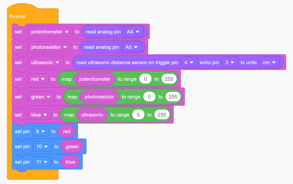
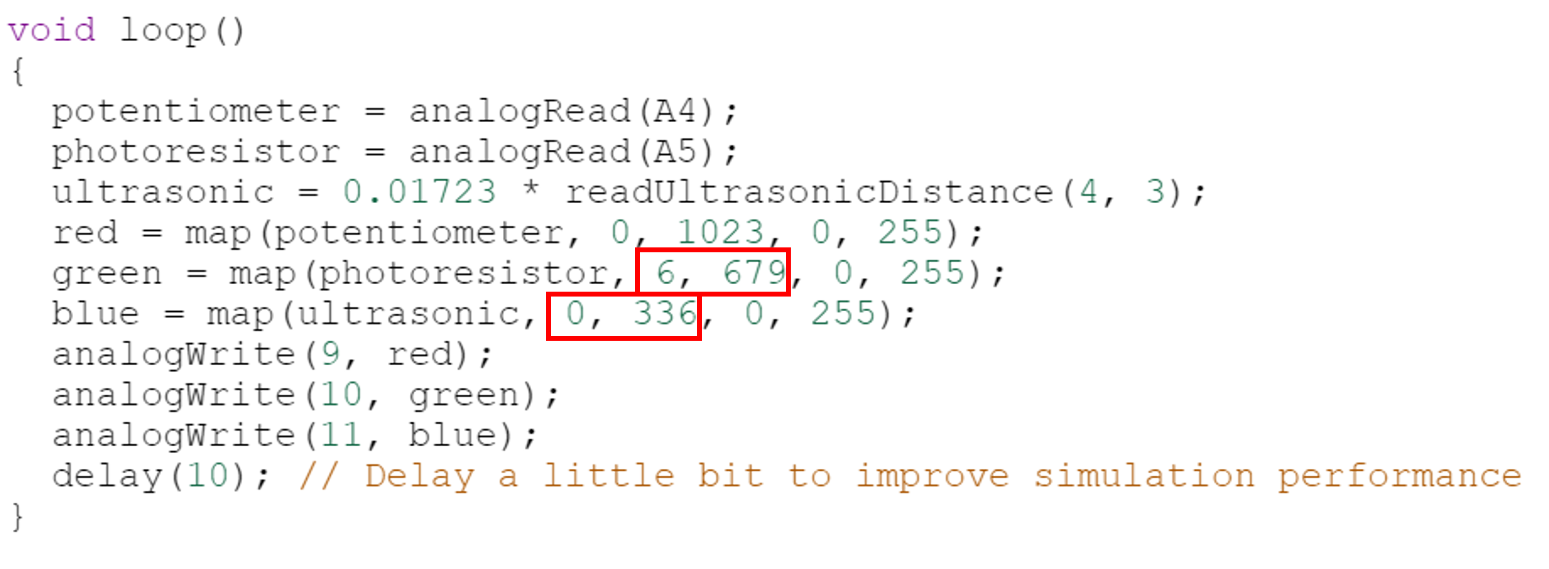
Map the potentiometer input to the red pin of the RGB LED, the LDR to the green pin, and the ultrasonic to the blue pin.
Tip: You can use the serial monitor to work out the ranges for these components.
As we are measuring inputs, create a variable for each of the components we're reading.
In the block-based program, the mapping has a default range setting for an input device of 0-1023. This may not match with all components. This means you will need to change the range by accessing the 'blocks + text' option at the top of the coding panel and making the necessary changes in the text - this was covered in Session Five's video.
If you are still stuck, please use the answer button below.
Block code:
Text code with changes highlighted:
Create an Arduino circuit with an ultrasonic sensor and a Peizo buzzer. Map the ultrasonic sensor value to the Peizo to create an electronic version of a theremin (see Wikipedia).